Pin configuration, 12-pin multi-connector (dc-in/gpi, Digital output connector for giga – JAI AD-081GE User Manual
Page 10: 6-pin multi-connector (lvds in an, Ad-081ge
AD-081GE
9
5. Pin configuration
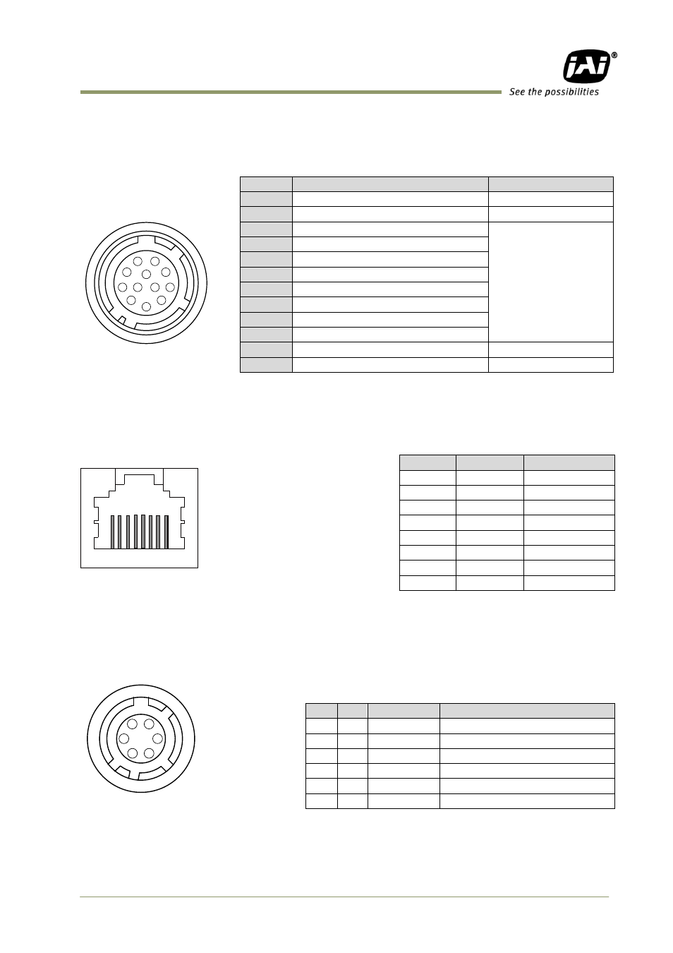
5.1. 12-pin Multi-connector (DC-in/GPIO/Iris Video)
Type: HR10A-10R-12PB
(Hirose) male.
(Seen from the rear of
camera)
Fig. 2. 12-pin connector.
5.2. Digital Output Connector for Gigabit Ethernet
Type: RJ-45 : HFJ11-1G02E-L21RL or equivalent
The digital output signals follow
the Gigabit Ethernet interface
using an RJ-45 conforming
connector. To the right is a table
with the pin assignment for
Gigabit Ethernet connector.
Fig. 3. Gigabit Ethernet
connector
5.3. 6-pin Multi-connector (LVDS IN and TTL IN/OUT)
Type : HR-10A-7R-6PB
注
Fig.4 HIROSE 6-pin connector *1:can be changed by DIP switches.
*2: Open collector or TTL level can be selected by an
internal DIP switch. Factory default is TTL.
Pin no.
Signal
Remarks
1
GND
2
+12 V DC input
3
Opt IN 2 (-) / GND (*1)
GPIO IN / OUT
4
Opt IN 2 (+)/Iris Video out (*1)
5
Opt IN 1 ( - )
6
Opt IN 1 ( + )
7
Opt Out 1 ( - )
8
Opt Out 1 ( + )
9
Opt Out 2 ( - )
10
Opt Out 2 ( + )
11
+ 12 V DC input
12
GND
*1: Iris Video output function can be set by the internal DIP switch
(SW700).
Pin No
In/Out
Name
1
In/Out
MX1+ (DA+)
2
In/Out
MX1- (DA-)
3
In/Out
MX2+ (DB+)
4
In/Out
MX3+ (DC+)
5
In/Out
MX3- (DC-)
6
In/Out
MX2- (DB-)
7
In/Out
MX4+ (DD+)
8
In/Out
MX4- (DD-)
No I/O
Name
Note
1
I
LVDS In 1-
2
I
LVDS In 1+
3
I
TTL IN 1
75ohm Terminator (Note*1)
4
O TTL Out 1 Note*2)
5
I
TTL IN 2
75ohm Terminator(Note*1)
6
GND
3
4
5
6
7
8
9
10
11
12
1
2
1
2
3
4
5
6
7
8
1
2
3
4
5
6