10 receiver buffer register (rbr), Figure 23. receiver buffer register (rbr), 11 divisor latch registers (dlm and dll) – Intel 537EX User Manual
Page 101: Figure 24. divisor latch registers (dlm and dll), Table 29. programmable data rates, Receiver buffer register (rbr), Divisor latch registers (dlm and dll), Programmable data rates, Intel confidential
536EX Chipset Developer’s Manual
101
Intel Confidential
Parallel Host Interface 16C450/16C550A UART
9.2.10
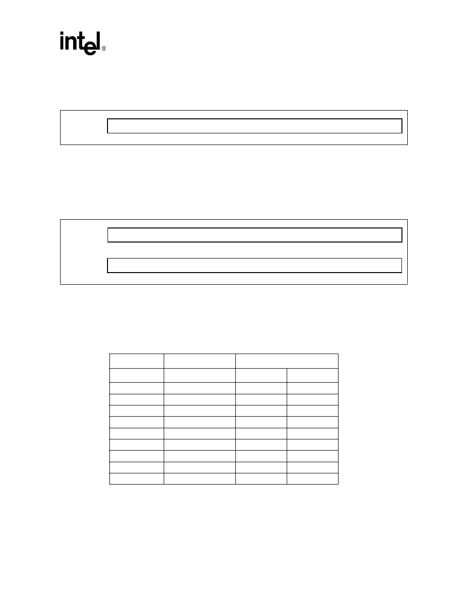
Receiver Buffer Register (RBR)
The RBR (Receiver Buffer register) is a read-only register used for receiving data and AT
command responses from the modem.
9.2.11
Divisor Latch Registers (DLM and DLL)
The LS divisor latch (least-significant byte) and MS divisor latch (most-significant byte) are two
read/write registers used to set the modem data rate. The data rate is selected by loading each
divisor latch with the appropriate hex value. The programmable data rates are provided in the
following table. For example, to use a data rate of 2400 bps, load a $00h into the DLM and a $30h
into the DLL.
Figure 23. Receiver Buffer Register (RBR)
RBR
Register 0
(DLAB = 0)
Figure 24. Divisor Latch Registers (DLM and DLL)
DLM (MS)
Register 1
(DLAB = 1)
DLL (LS)
Register 0
(DLAB = 1)
Table 29. Programmable Data Rates
Data Rate
Divisor Number
Divisor Latch (Hex)
(Decimal)
MS
LS
300
384
01
80
1200
96
00
60
2400
48
00
30
4800
24
00
18
7200
16
00
10
9600
12
00
0C
19200
6
00
06
38400
3
00
03
57600 2
00
02