Impex IGS 16 User Manual
Page 18
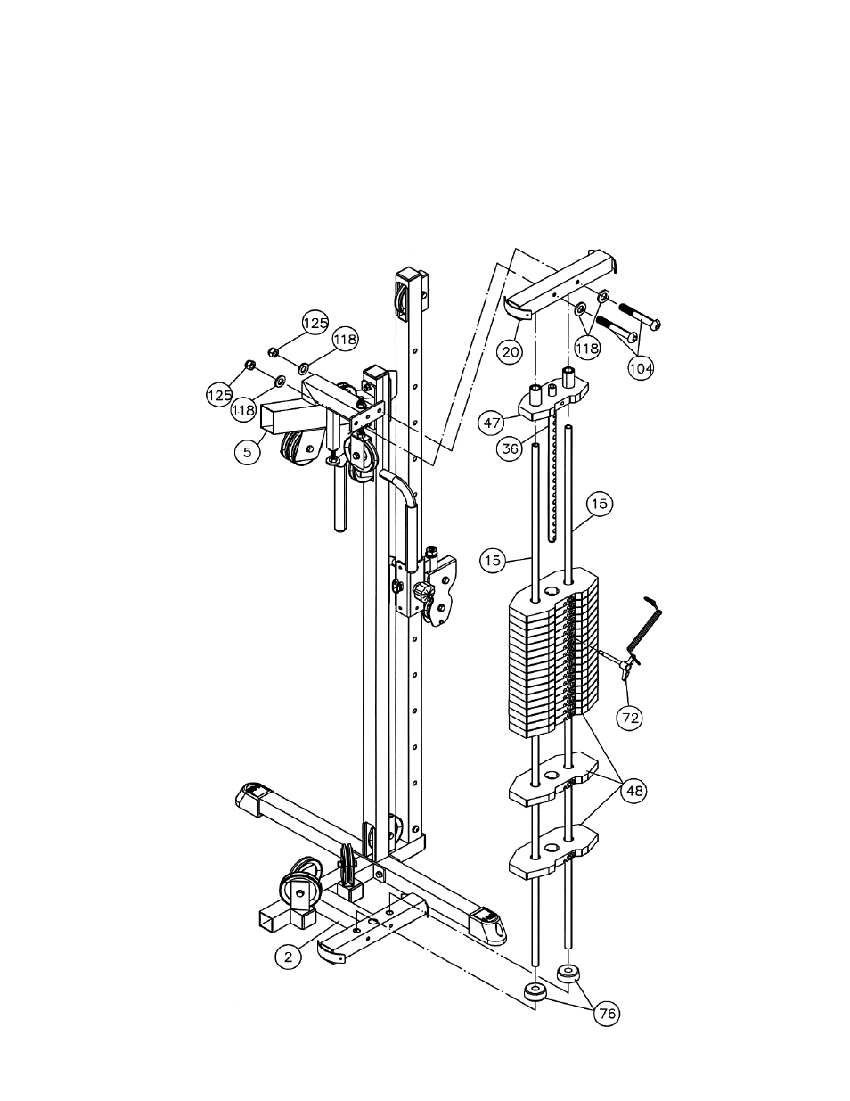
STEP 11 (See Diagram 11)
A.) Align two Ø 2 ½” x 1” Rubber Bumpers (#76) onto the holes on the Main Base Frame (#2).
Insert two Guide Rods (#15) through the Bumpers and into the Base Frame. Slide 19 Weight
Plates (#48) onto the Guide Rods.
B.) Slide the Selector Stem (#47) with the Selector Rod (#36) onto the Guide Rods. Insert the
Selector Rod (#36) through the center hole.
C.) Insert a Weight Plate Selector Pin (#72) through the selected hole on the Weight Plates.
D.) Place the Top Socket Assembly (#20) onto the Guide Rods. Secure it to the Upper Frame (#5)
with two M10 x 2 ¾” Allen Bolts (#104), four Ø ¾” Washers (#118), and two M10 Aircraft Nuts
(#125).
17
See also other documents in the category Impex Sports and recreation:
- IGS-09 (11 pages)
- SAG-44.1 (10 pages)
- TSA-5682 (14 pages)
- MWM-1840 (29 pages)
- IGS-10 (10 pages)
- TC-6000 (12 pages)
- MWB-715N (12 pages)
- CR 5 (26 pages)
- MD-823 (15 pages)
- PL-43211 (14 pages)
- PL 10510 (12 pages)
- WM-1505 (22 pages)
- PHE1000 (20 pages)
- TSA-5762 (14 pages)
- IGS-5683 (13 pages)
- DBR 400 (7 pages)
- MWM7150 (21 pages)
- DBR 90 (11 pages)
- CG 1400 (24 pages)
- SB 208 (9 pages)
- IGS-02 (10 pages)
- MWB-356 (13 pages)
- AX-PWR7 (21 pages)
- MWB-855 (11 pages)
- TSA-410 (10 pages)
- TSA-41 (7 pages)
- WM 1403 (22 pages)
- DBR 92 (11 pages)
- MARCY TPL-40 (3 pages)
- MSS-1280 (27 pages)
- JD 2 (8 pages)
- PHC-700 (12 pages)
- Gold's Gym WMGG-224 (11 pages)
- MWM 800 (23 pages)
- WM-356 (13 pages)
- EVE-720 (13 pages)
- BF-1201 (22 pages)
- PT 360 (9 pages)
- CB-200 (11 pages)
- Olympic Cage (24 pages)
- EVE-900 (21 pages)
- PT-36 (7 pages)
- PHC-PWR9 (22 pages)
- MWM-1558 (20 pages)
- MWB-4360 (33 pages)