Impex IGS 16 User Manual
Page 17
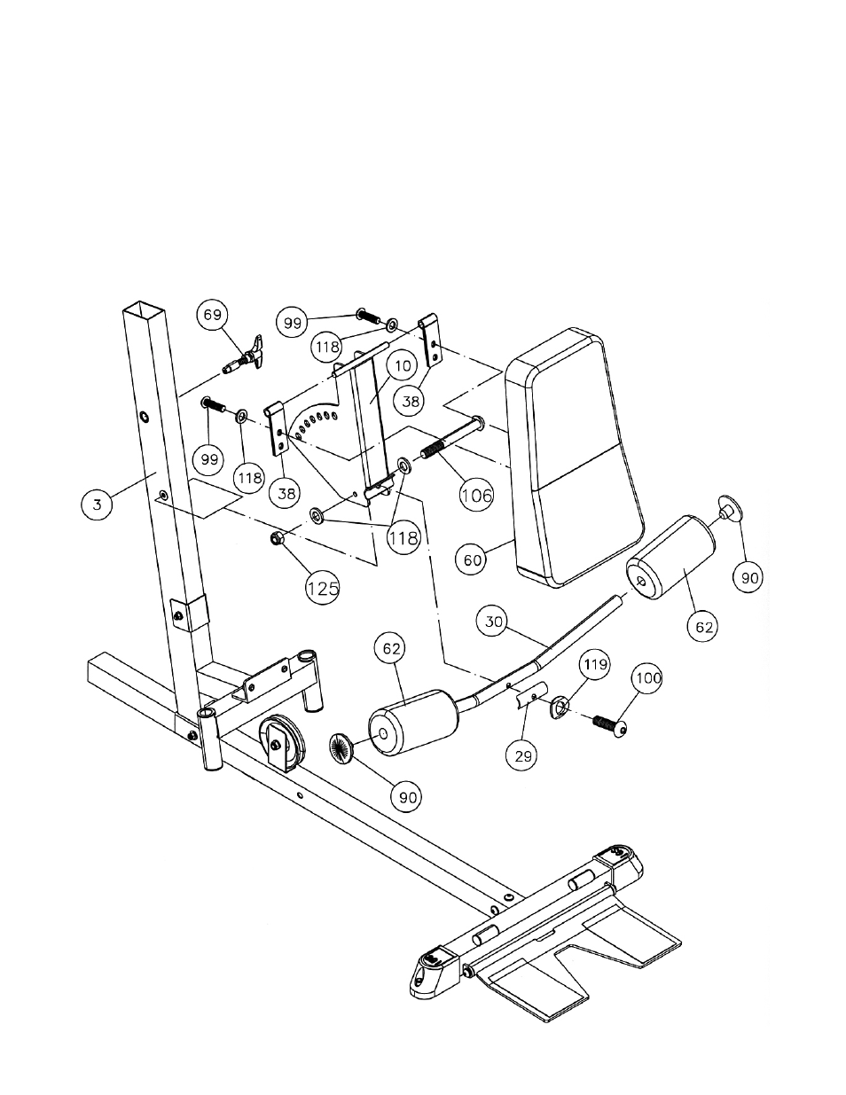
STEP 10 (See Diagram 10)
A.) Attach the Backrest Adjustment Frame (#10) to the Front Vertical Beam (#3). Secure the
bottom of the Frame to the Front Vertical Beam with one M10 x 3 1/8” Allen Bolt (#106), two Ø
¾” Washers (#118), and one M10 Aircraft Nut (#125).
B.) Attach two Backrest Swivel Brackets (#38) to the pivot on the Frame. Attach the Backrest Board
(#60) to the Brackets. Secure the Board with two M10 x 1 1/8” Allen Bolts (#99) and Ø ¾”
Washers (#118).
C.) Thread a T-shaped Pull Pin Set (#69) through the hole on the Front Vertical Beam (#3) to obtain
the desired Backrest position.
D.) Attach the Angled Foam Tube (#30) to the Backrest Adjustment Frame (#10). Secure it with
one Bent Bracket (#29), M10 x 1 5/8” Allen Bolt (#100) and Ø 7/8” Bent Washer (#119).
E.) Push two Foam Rolls (#62) onto the Tube from both ends. Push two Foam Roll End Caps
(#90) into the ends.
16
- IGS-09 (11 pages)
- SAG-44.1 (10 pages)
- TSA-5682 (14 pages)
- MWM-1840 (29 pages)
- IGS-10 (10 pages)
- TC-6000 (12 pages)
- MWB-715N (12 pages)
- CR 5 (26 pages)
- MD-823 (15 pages)
- PL-43211 (14 pages)
- PL 10510 (12 pages)
- WM-1505 (22 pages)
- PHE1000 (20 pages)
- TSA-5762 (14 pages)
- IGS-5683 (13 pages)
- DBR 400 (7 pages)
- MWM7150 (21 pages)
- DBR 90 (11 pages)
- CG 1400 (24 pages)
- SB 208 (9 pages)
- IGS-02 (10 pages)
- MWB-356 (13 pages)
- AX-PWR7 (21 pages)
- MWB-855 (11 pages)
- TSA-410 (10 pages)
- TSA-41 (7 pages)
- WM 1403 (22 pages)
- DBR 92 (11 pages)
- MARCY TPL-40 (3 pages)
- MSS-1280 (27 pages)
- JD 2 (8 pages)
- PHC-700 (12 pages)
- Gold's Gym WMGG-224 (11 pages)
- MWM 800 (23 pages)
- WM-356 (13 pages)
- EVE-720 (13 pages)
- BF-1201 (22 pages)
- PT 360 (9 pages)
- CB-200 (11 pages)
- Olympic Cage (24 pages)
- EVE-900 (21 pages)
- PT-36 (7 pages)
- PHC-PWR9 (22 pages)
- MWM-1558 (20 pages)
- MWB-4360 (33 pages)