Impex IGS 16 User Manual
Page 14
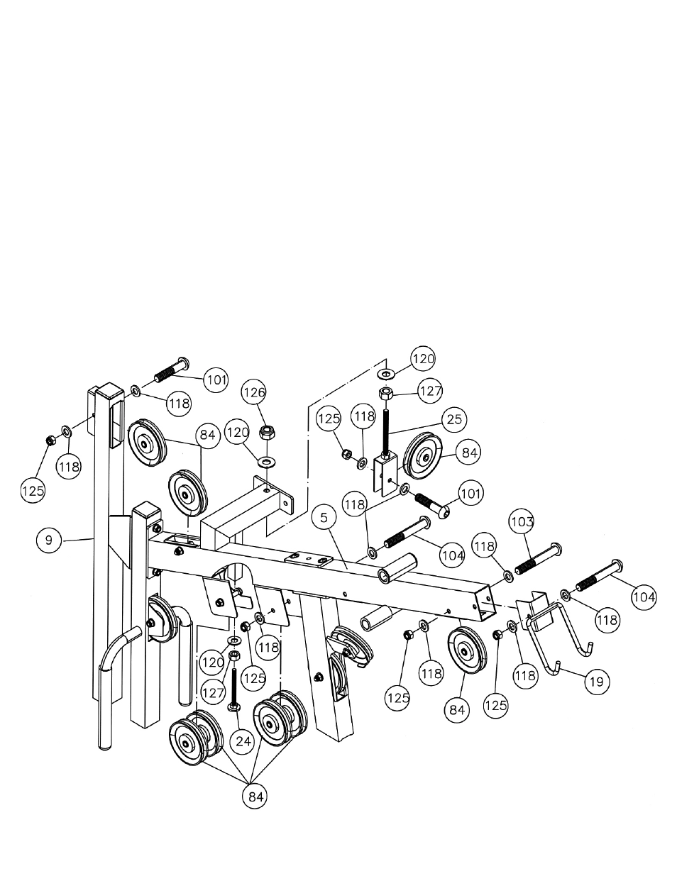
STEP 7 (See Diagram 7)
A.) Attach a Pulley to the front opening on the Upper Frame (#5). Secure it with one M10 x 2 ½”
Allen Bolt (#103), two Ø ¾” Washers (#118), and one M10 Aircraft Nut (#125). Do not tighten
the nut and bolt yet. The Pulley needs to be removed to install the cable later.
B.) Attach the Lat Bar Holder (#19) to the Upper Frame. Secure it with one M10 x 2 ¾” Allen Bolt
(#104), two Ø ¾” Washers (#118), and one M10 Aircraft Nut (#125).
C.) Attach two Pulleys to the open bracket underneath the Upper Frame. Secure them with one
M10 x 2 ¾” Allen Bolt (#104), two Ø ¾” Washers (#118), and one M10 Aircraft Nut (#125).
Repeat the same step to install the other two Pulleys to the other open bracket underneath the
Upper Frame.
D.) Attach a Pulley to the opening on the Upper Frame and top of Sliding Pulley Vertical Beam (#9).
Secure each Pulley with one M10 x 1 ¾” Allen Bolt (#101), two Ø ¾” Washers (#118), and one
M10 Aircraft Nut (#125).
E.) Thread a Pulley Pre-tensioner (#24) into the hole underneath the Upper Frame and secure it
with one M12 Regular Nut (#127) and Ø1 1/8”xØ ½” Washer (#120). Do not tighten the nut yet.
F.) Attach a Pulley to the Adjustable Single Pulley Bracket (#25). Secure it with one M10 x 1 ¾”
Allen Bolt (#101), two Ø ¾” Washers (#118), and one M10 Aircraft Nut (#125).
G.) Insert the Adjustable Single Pulley Bracket (#25) through the hole on the Upper Frame. Secure
it with two Ø 1 1/8” x Ø ½” Washers (#120), one M12 Regular Nut (#127) and one M12 Aircraft
Nut (#126). Do not tighten the nuts yet.
13