Diagram 4 – Impex IGS 16 User Manual
Page 11
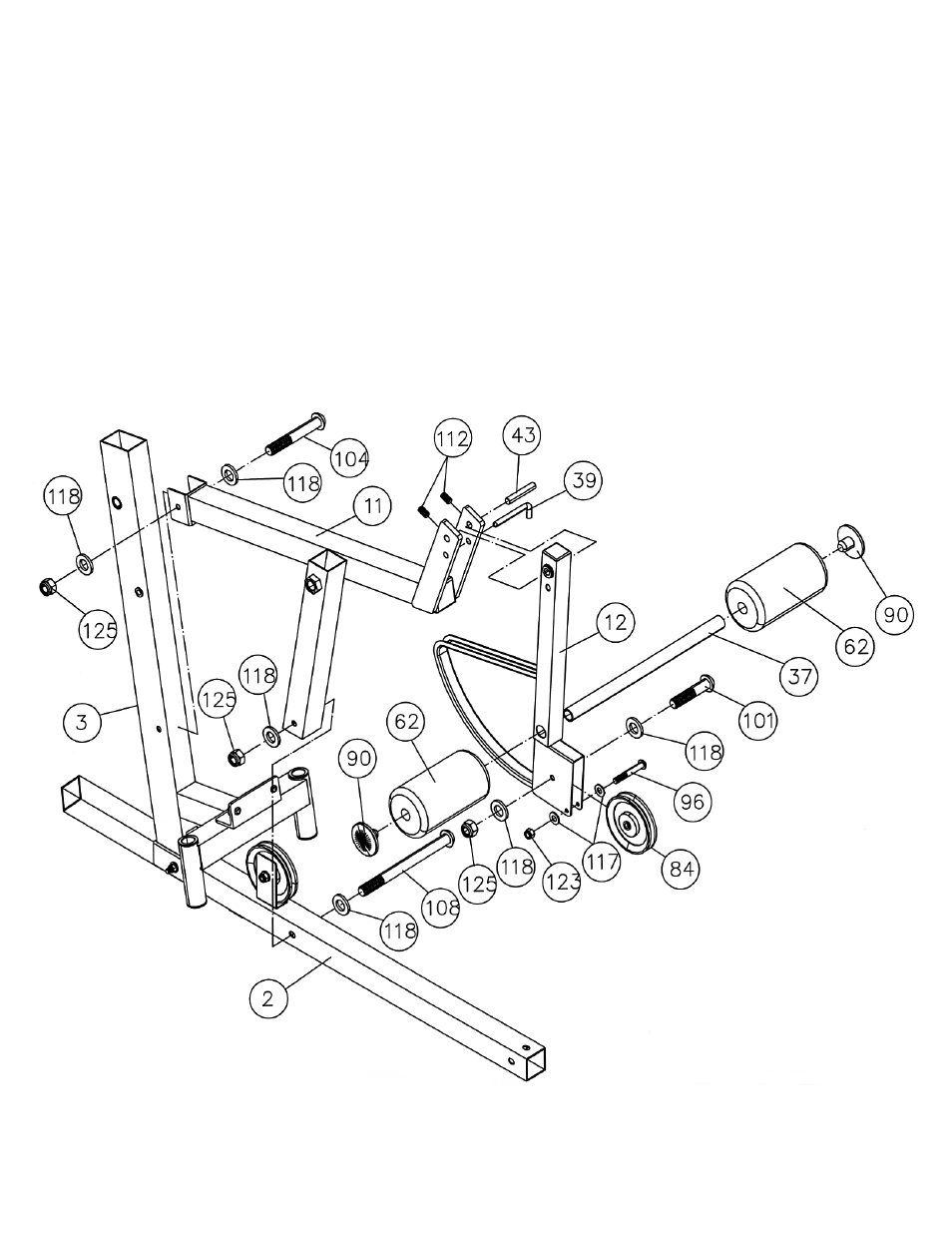
STEP 4 (See Diagram 4)
A.) Attach the Seat Support (#11) to the Front Vertical Beam (#3) and Main Base Frame (#2).
Secure it to the Front Vertical Beam with one M10 x 2 ¾” Allen Bolt (#104), two Ø ¾” Washers
(#118), and one M10 Aircraft Nut (#125). Secure it to the Main Base Frame with one M10 x 4 ½”
Allen Bolt (#108), two Ø ¾” Washers (#118), and one M10 Aircraft Nut (#125).
B.) Attach the Leg Developer (#12) to the Seat Support. Align the holes and insert a 2 ¾” Leg
Developer Axle (#43). Secure the Axle with two M6 x 3/8” Socket Set Screws (#112). Insert a 4”
L-shaped Pin (#39) to lock the Leg Developer in place. Remove the Pin when doing Leg
Developer exercises.
C.) Insert a Foam Tube (#37) halfway through the hole on the Leg Developer. Push two Foam Rolls
(#62) onto the Tube from both ends. Push two Foam Roll End Caps (#90) into the ends.
D.) Attach a Pulley to the open bracket on the Leg Developer. Secure it with one M10 x 1 ¾” Allen
Bolt (#101), two Ø ¾” Washers (#118), and one M10 Aircraft Nut (#125). Insert a M6 x 1 5/8”
Allen Bolt (#96) through the holes on the bracket and secure it with two Ø ½” Washers (#117)
and one M6 Aircraft Nut (#123).
DIAGRAM 4
10