Impex IGS 16 User Manual
Page 13
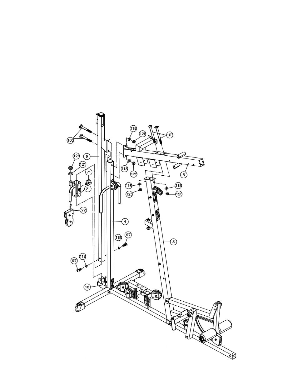
STEP6 (See Diagram 6)
A.) Slide the Sliding Pulley Frame (#21) onto the Sliding Pulley Vertical Beam (#9) from the bottom.
Use a Lock Knob (#71) to secure the Frame at desired position.
B.) Attach the Sliding Pulley Vertical Beam (#9) onto the Rear Base (#18). Secure it with two M10 x
¾” Allen Bolts (#97) and Ø ¾” Washers (#118). Do not tighten the bolts yet.
C.) Place the Upper Frame (#5) onto the Front Vertical Beam (#3). Secure it with two M10 x 4”
Carriage Bolts (#107), Ø ¾” Washers (#118), and M10 Aircraft Nuts (#125). Do not tighten the
nuts and bolts yet.
D.) Attach the Upper Frame (#5) to the Rear Vertical Frame (#4). Align them to the Sliding Pulley
Vertical Beam (#9). Secure them together with two M10 x 3” Carriage Bolts (#105), Ø ¾”
Washers (#118), and M10 Aircraft Nuts (#125). Do not tighten the nuts and bolts yet.
E.) Insert the axle on the Sliding Pulley Bracket (#22) into the pivot on the Sliding Pulley Frame
(#21). Secure it with one Ø 1 ¼” x Ø 5/8” Washer (#121) and M16 Regular Nut (#128). Make
sure the Bracket is able to swivel.
12