Impex IGS 16 User Manual
Page 16
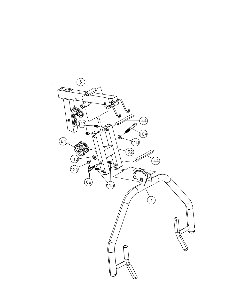
STEP 9 (See Diagram 9)
A.) Attach the Bench Press Base (#32) to the pivot on the Upper Frame (#5). Align the holes and
insert a 8” Bench Press Axle (#44) through the holes. Secure the Axle with two M10 x ½”
Socket Set Screws (#113).
B.) Attach the Bench Press Arm (#1) to the Bench Press Base (#32). Align the holes and insert a
8” Bench Press Axle (#44) through the holes. Secure the Axle with two M10 x ½” Socket Set
Screws (#113).
C.) Thread a T-shaped Pull Pin Set (#69) through the hole on the Bench Press Base (#32) to obtain
the desired Bench Press position.
D.) Attach two Pulleys (#84) to the open bracket on the back of Bench Press Base (#32). Secure
them with one M10 x 2 ¾” Allen Bolt (#104), two Ø ¾” Washers (#118), and one M10 Aircraft
Nut (#125).
15
- IGS-09 (11 pages)
- SAG-44.1 (10 pages)
- TSA-5682 (14 pages)
- MWM-1840 (29 pages)
- IGS-10 (10 pages)
- TC-6000 (12 pages)
- MWB-715N (12 pages)
- CR 5 (26 pages)
- MD-823 (15 pages)
- PL-43211 (14 pages)
- PL 10510 (12 pages)
- WM-1505 (22 pages)
- PHE1000 (20 pages)
- TSA-5762 (14 pages)
- IGS-5683 (13 pages)
- DBR 400 (7 pages)
- MWM7150 (21 pages)
- DBR 90 (11 pages)
- CG 1400 (24 pages)
- SB 208 (9 pages)
- IGS-02 (10 pages)
- MWB-356 (13 pages)
- AX-PWR7 (21 pages)
- MWB-855 (11 pages)
- TSA-410 (10 pages)
- TSA-41 (7 pages)
- WM 1403 (22 pages)
- DBR 92 (11 pages)
- MARCY TPL-40 (3 pages)
- MSS-1280 (27 pages)
- JD 2 (8 pages)
- PHC-700 (12 pages)
- Gold's Gym WMGG-224 (11 pages)
- MWM 800 (23 pages)
- WM-356 (13 pages)
- EVE-720 (13 pages)
- BF-1201 (22 pages)
- PT 360 (9 pages)
- CB-200 (11 pages)
- Olympic Cage (24 pages)
- EVE-900 (21 pages)
- PT-36 (7 pages)
- PHC-PWR9 (22 pages)
- MWM-1558 (20 pages)
- MWB-4360 (33 pages)