IBM BDM-610000049 User Manual
Page 37
BDM-610000049
Rev G
Chapter 3: Connecting the cpuModule
27
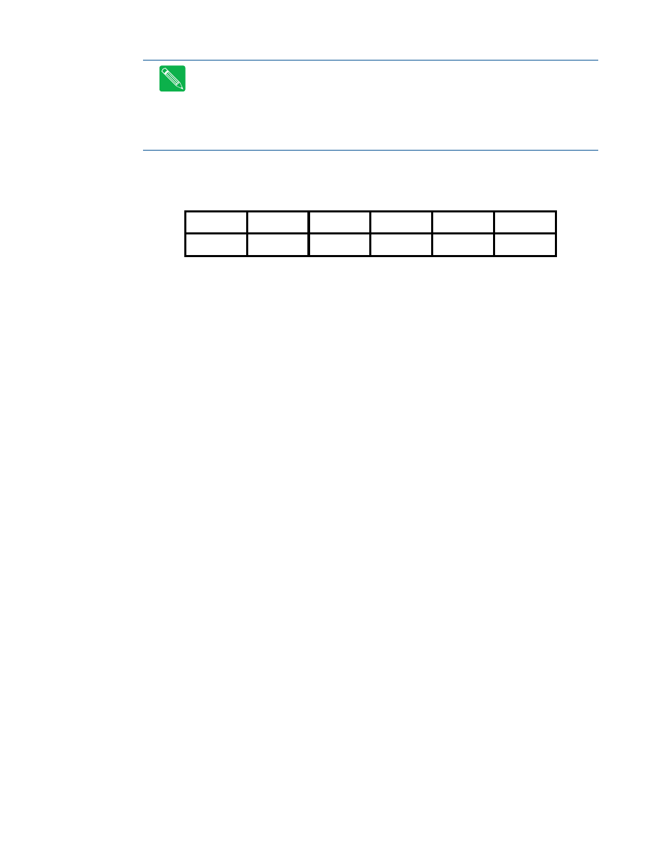
Facing the connector pins, the pinout of the Auxiliary Power connector is:
Note
The +3.3 V pins (10 and 12) on the auxiliary power connector (CN3) are connected to the +3.3 V
pins on the PC/104-Plus bus by default. These pins are also configured to supply +3.3V to FP_VCC on the
LVDS Flat Panel Video connector (CN19).
Note
For more information on configuring the +3.3V pins on the auxiliary power connector (CN3) the
PCI bus connector (CN16), or the LVDS FLat Panel Video connector (CN19), contact RTD Technical
Support.
11
9
7
5
3
1
PSON#
GND
GND
Reserved
+5V_STDBY
GND
+3.3 V
+3.3 V
+5 V
–12 V
+12 V
+5 V
12
10
8
6
4
2
See also other documents in the category IBM Computer Accessories:
- ZG09-0629 (24 pages)
- 8271 F24 (2 pages)
- DS3200 (18 pages)
- X3850 M2 (19 pages)
- 12.1(22)EA6 (550 pages)
- SG24-4817-00 (316 pages)
- Data Server DB2 (298 pages)
- Nortel 10 (90 pages)
- 6 MPLS (22 pages)
- 614 (2 pages)
- WAVV 2004 (21 pages)
- CMX58886CX (110 pages)
- Volition Dual Speed Mini-Hub VOL-2008 (3 pages)
- 25CPC710 (8 pages)
- BM 8270 (8 pages)
- 2X16 (18 pages)
- NWAYS 712 (2 pages)
- REDBOOKS B24X (22 pages)
- AT-FS202 (44 pages)
- X3400 (16 pages)
- 190000 (19 pages)
- THINKPAD S05L-1270-01 (716 pages)
- 8260 (25 pages)
- E (40 pages)
- 6633 - 4LE (19 pages)
- RS/6000 SP (114 pages)
- SAN32M-2 (8 pages)
- 19K4260 (105 pages)
- 8276 (4 pages)
- POWERPC 750GX (377 pages)
- DB2 Everyplace 7.2.1 (18 pages)
- ATM OC-3c (140 pages)
- iSeries 270 and 820 SENG-3002-01 (30 pages)
- AA-RWF3A-TE (159 pages)
- 524 (2 pages)
- 24R9718 IB (59 pages)
- 8271 (6 pages)
- 02L1333 (6 pages)