Proper grounding techniques, Connector locations – IBM BDM-610000049 User Manual
Page 34
24
CMX158886 cpuModule
BDM-610000049
Rev G
Proper Grounding Techniques
Before removing the CMX158886 from its static bag, proper grounding techniques must be used to prevent
electrostatic discharge (ESD) damage to the cpuModule. Common grounding procedures include an anti-static
mat on a workbench, which may connect to an anti-static wrist strap (also known as an ESD wrist strap) on the
wrist of the technician or engineer.
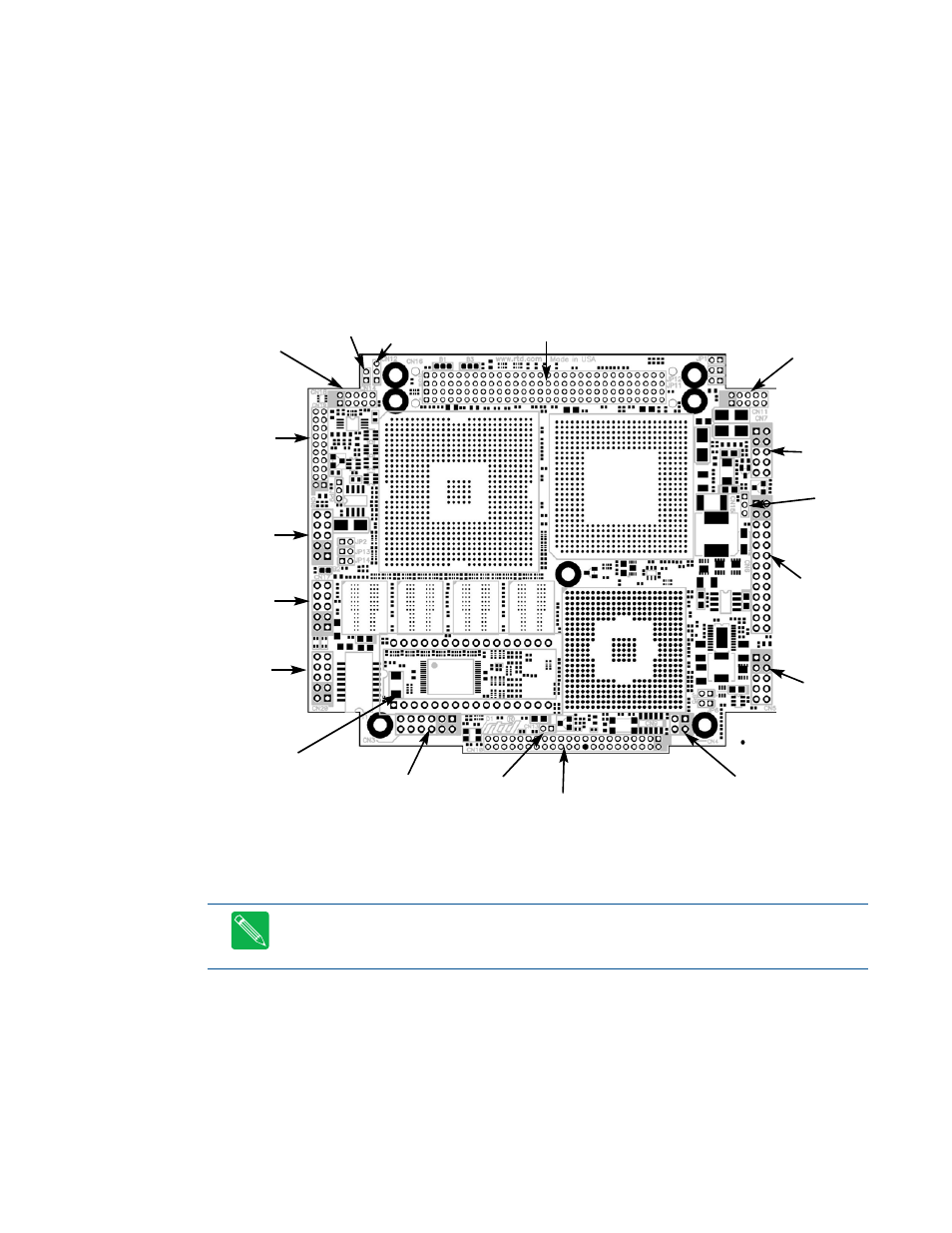
Connector Locations
Figure 4 shows the connectors and the ATA/IDE Disk Chip socket of the CMX158886 cpuModule.
Figure 4
CMX158886 Connector Locations
Note
Pin 1 of each connector is indicated by a white silk-screened square on the top side of the board
and a square solder pad on the bottom side of the board. Pin 1 of the bus connectors match when
stacking PC104-Plus or PCI-104 modules.
ATA/IDE
Disk Chip
(U16)
PCI Bus (CN16)
COM1
(CN7)
COM2
(CN8)
SVGA
Video
(CN18)
EIDE (CN10)
Auxiliary Power
(CN3)
Multi-
Function
(CN5)
multiPort
(CN6)
LVDS Flat
Panel
(CN19)
Ethernet
(CN20)
USB 2.0
(CN17)
Audio
(CN11)
ISA Bridge Link
(CN4)
Cont. Fan
(CN14)
Power
Mngmt.
(CN12)
Switched
Fan
(CN15)
Battery
(CN13)