1 led and button table, 2 connector table, Led function – Minicom Advanced Systems Minicom Smart 116 IP User Manual
Page 8: Button, Function, Connector function
SMART 108/116 IP
7
7.1 LED and button table
LED
Function
Power
Power Indicator
Remote
Illuminates when remote session is active
Link
Unit is connected to the network
Button
Function
Local
When pressed, Smart 108/116 IP disconnects the Client remote
session and the local mouse and keyboard become operational. The
Remote LED turns off.
Reset
Press and hold for more than 7 seconds to reset the Smart 108/116 IP
unit
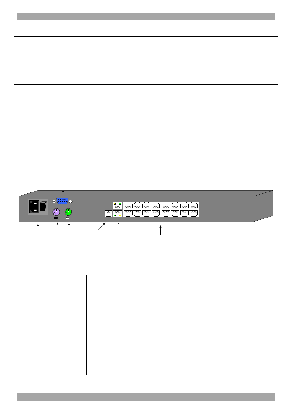
Figure 2 illustrates the rear panel of the Smart 108/116 IP. The Smart 108 IP has 8
Server ports.
Power
connector
POWER
100-240 VAC 50/60 Hz
Server ports
I
0
1
2
3
4
5
6
7
8
10
11
12
13
14
15
16
9
Keyboard
Mouse
Monitor
CONSOLE
LAN (Ethernet)
connector
FLASH
LAN
SERIAL
Flash
(download)
connector
Figure 2 Smart 108/116 IP rear panel
7.2 Connector table
Connector
Function
Console KVM
(Optional) Connect a keyboard, video and mouse to operate the
Smart 108/116 IP locally
Serial
This port is for future Serial functionality
Flash
To update firmware of the analogue part of the Smart 108/116 IP
system - OSD, Switch, RICCs and RoCs.
LAN
Connect to 10/100 Mbit Ethernet. Green LED illuminates when
unit is connected to a 100 Mbit/sec network. Yellow Led
illuminates when unit is connected to a 10 Mbit/sec network.
Server ports
Connect to servers via RICC/ROCs