Motorola PR400 User Manual
Page 82
July, 2004
6881096C24-A
7-14 Limited Keypad Model Disassembly and Re-assembly: Disassembling and Re-assembling the Radio — General
a.
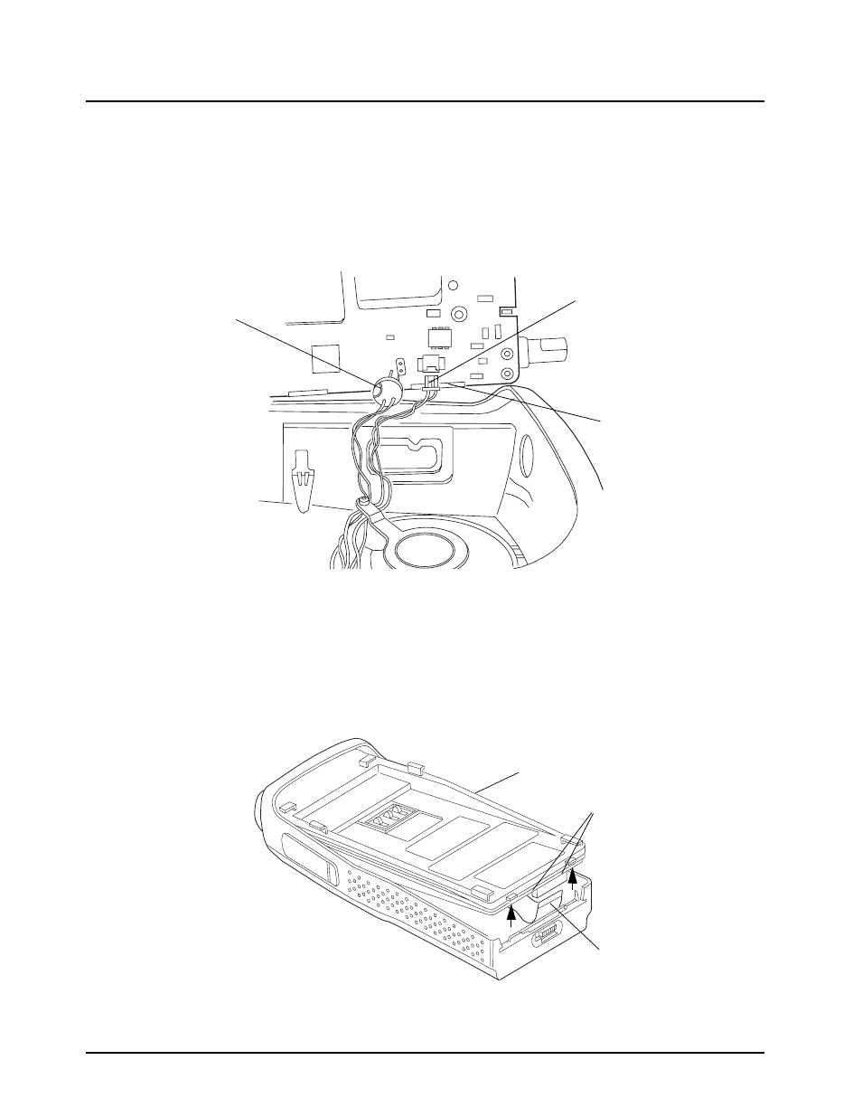
Connect the speaker wire assembly into the 2-pin connector on the main board and
bend the wires at the board connector so the wires are positioned toward the top of the
radio (
b.
Connect the microphone wire assembly into the two hole socket on the main board and
bend the wires at the board connector so the wires are positioned toward the top of the
radio (
c.
Slide the audio jack shroud onto accessory connector
(
Figure 7-17
).
2.
Position the radio (
) and reconnect the flex cable connector from the keyboard into the
connector located on the bottom of the main board, pushing up the 2 end tabs.
3.
Slide the volume potentiometer and frequency switch shafts into their respective holes in the front
cover. Look through the accessory connector opening to make certain that the wires are not
pinched, between the shroud and housing.
Figure 7-18. Microphone and Speaker Wires
Figure 7-19. Keyboard Flex Cable Connection
Speaker Connector
Microphone
Connector
Shroud
Radio Chassis
Flex Cable Connector
End Tabs