6 chassis and front cover re-assembly – Motorola PR400 User Manual
Page 63
6881096C24-A
August, 2004
Full Keypad Model Disassembly and Re-assembly: Disassembling and Re-assembling the Radio — General
6-13
b.
If you have the newer chassis (2786389Z02) use the newer O-ring (3286431Z05). Posi-
tion the O-ring with the plug on the right side (speaker connector side). Push the plug all
the way into the chassis slot until it is touching the chassis flange. Repeat for the left
side. Stretch the O-ring to place it into the retaining groove at the top and bottom end of
the chassis.
6.
Check that the O-ring is not twisted and being held by the top and bottom chassis groves.
.
6.4.2.6 Chassis and Front Cover Re-assembly
1.
Dress and connect the speaker wires..
a.
Connect the speaker wire assembly into the 2-pin connector on the main board and
bend the wires at the board connector so the wires are positioned toward the top of the
radio (
b.
Connect the microphone wire assembly into the two hole socket on the main board and
bend the wires at the board connector so the wires are positioned toward the top of the
radio (
c.
Slide the audio jack shroud onto accessory connector (
Figure 6-17
).
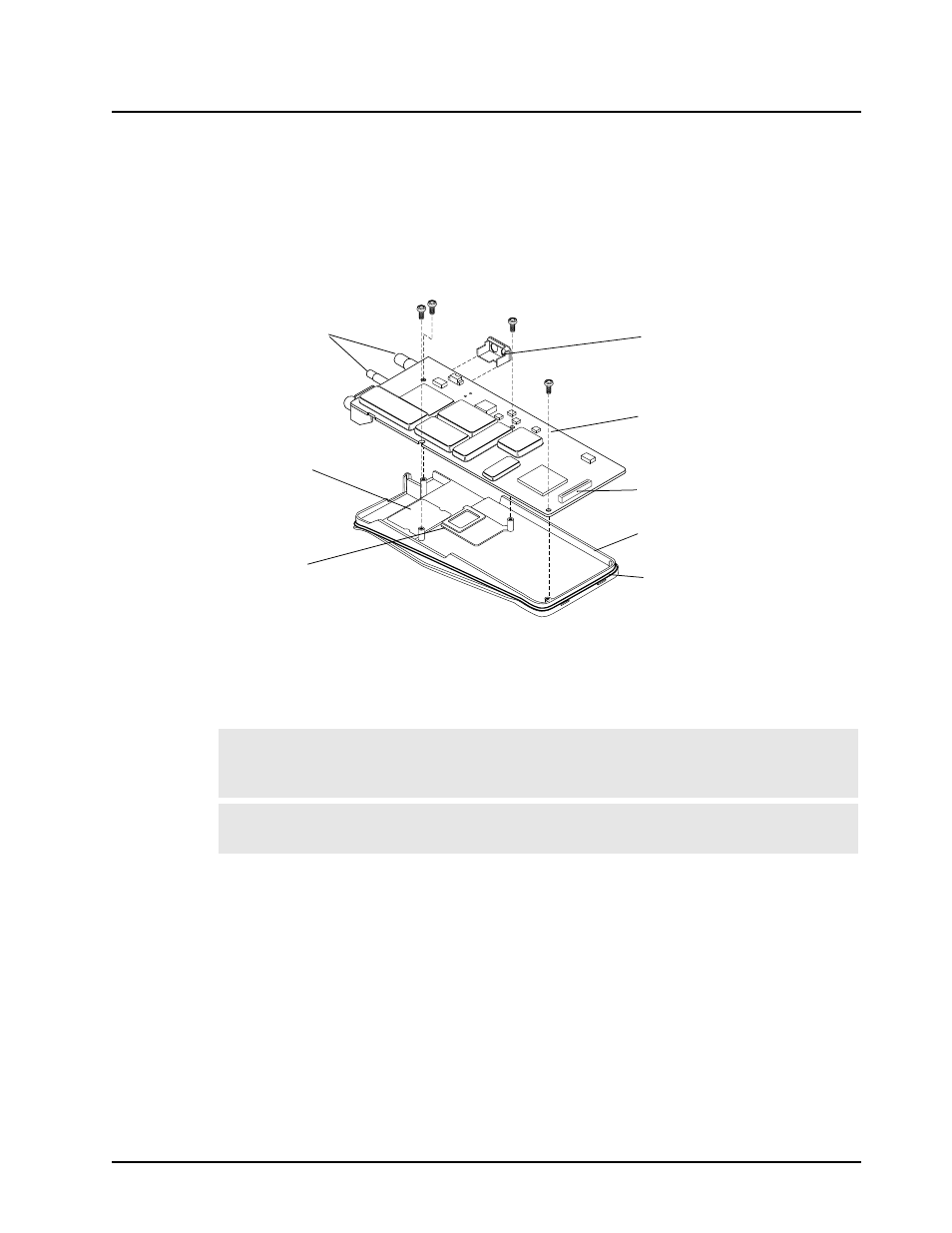
Figure 6-17. Main Board onto Chassis Re-assembly
Note: Care should be taken when dressing the speaker and microphone wires to avoid pinching
them between the speaker magnet and shield, or between the accessory connector and
housing.
Note: Ensure that the plug orientation is correct with the exposed pins in the wire casing facing
upward and fully plugged in.
Main Board
Radio Chassis
Flex Cable Connector
Battery Contact Seal
Interface Pad
Frequency &
Volume Switches
Audio Jack Shroud
(Replace after Plugging
in Speaker and Mic)
O-Ring