Asynchronous memory timing, See figure 27−figure 28), See figure 27–figure 28) – Motorola TMS320C6711D User Manual
Page 71
TMS320C6711D
FLOATINGĆPOINT DIGITAL SIGNAL PROCESSOR
SPRS292A − OCTOBER 2005 − REVISED NOVEMBER 2005
71
POST OFFICE BOX 1443
•
HOUSTON, TEXAS 77251−1443
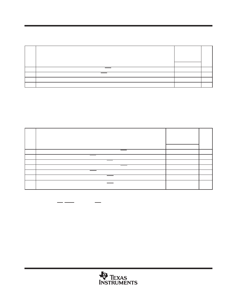
ASYNCHRONOUS MEMORY TIMING
timing requirements for asynchronous memory cycles
†‡§
(see Figure 27−Figure 28)
NO.
GDPA-167
ZDPA−167
−200
−250
UNIT
MIN
MAX
3
tsu(EDV-AREH)
Setup time, EDx valid before ARE high
6.5
ns
4
th(AREH-EDV)
Hold time, EDx valid after ARE high
1
ns
6
tsu(ARDY-EKOH)
Setup time, ARDY valid before ECLKOUT
high
3
ns
7
th(EKOH-ARDY)
Hold time, ARDY valid after ECLKOUT
high
2.3
ns
† To ensure data setup time, simply program the strobe width wide enough. ARDY is internally synchronized. The ARDY signal is recognized in
the cycle for which the setup and hold time is met. To use ARDY as an asynchronous input, the pulse width of the ARDY signal should be wide
enough (e.g., pulse width = 2E) to ensure setup and hold time is met.
‡ RS = Read setup, RST = Read strobe, RH = Read hold, WS = Write setup, WST = Write strobe, WH = Write hold. These parameters are
programmed via the EMIF CE space control registers.
§ E = ECLKOUT period in ns
switching characteristics over recommended operating conditions for asynchronous memory
cycles
†‡§
(see Figure 27–Figure 28)
NO.
PARAMETER
GDPA-167
ZDPA−167
−200
−250
UNIT
MIN
MAX
1
tosu(SELV-AREL)
Output setup time, select signals valid to ARE low
RS*E − 1.7
ns
2
toh(AREH-SELIV)
Output hold time, ARE high to select signals invalid
RH*E − 1.7
ns
5
td(EKOH-AREV)
Delay time, ECLKOUT high to ARE valid
1.5
7
ns
8
tosu(SELV-AWEL)
Output setup time, select signals valid to AWE low
WS*E − 1.7
ns
9
toh(AWEH-SELIV)
Output hold time, AWE high to select signals and EDx invalid
WH*E − 1.7
ns
10
td(EKOH-AWEV)
Delay time, ECLKOUT high to AWE valid
1.5
7
ns
11
tosu(EDV-AWEL)
Output setup time, ED valid to AWE low
(WS−1)*E −
1.7
ns
† RS = Read setup, RST = Read strobe, RH = Read hold, WS = Write setup, WST = Write strobe, WH = Write hold. These parameters are
programmed via the EMIF CE space control registers.
‡ E = ECLKOUT period in ns
§ Select signals include: CEx, BE[3:0], EA[21:2], and AOE.