Connecting additional devices, Input connections, Receiver – GTO UL325 SERIES User Manual
Page 34: Master inputs, 18v ac so la r rel ay ou t sla ve inputs
31
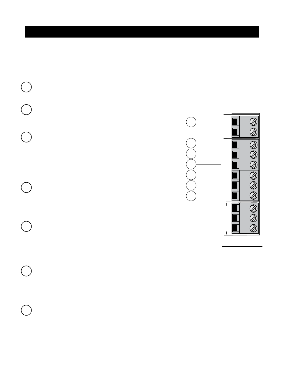
1 COM: Circuit common (reference for all logic input)
• Two (2) terminals to provide extra common connection point.
2 CYCLE CLOSE: (Typically for use with doorbell button or hardwired key pad)
• Each activation at this input will cycle the operation as follows:
….→ OPEN → STOP → CLOSE → STOP → OPEN → …
3 SAFETY: (Typically for use with photo beam device, loop detector
or other non-contact sensors)
• Activation of this input while the gate is closing will cause the gate to
stop and return to the opened position.
• Activation of this input while the gate is opening has no effect (gate
will continue to open).
• Activation of this input while gate is idle will prevent gate from closing.
4 EXIT/OPEN: (Typically for use with exit loop or wand)
• Activation of this input will open the gate if it’s not already at the
open position
• Activation of this input while at open limit will restart the auto close time
(if enabled).
5 SHADOW LOOP: (Typically for use with loop detector device)
• This input is only monitored when the gate is at the fully open
position. At any other position, activation of this input has no effect on
gate operation.
• Activation of this input while gate at the fully open position will
prevent gate from closing.
6 CLOSE EDGE: (Typically for use with safety edge device)
• Activation of this input while the gate is closing will cause the gate to
stop and reverse direction for approximately 2 seconds.
• Activation of this input while the gate is opening has no effect (gate will continue to open).
• Activation of this input while gate is idle will prevent gate from closing.
7 OPEN EDGE: (Typically for use with safety edge device)
• Activation of this input while the gate is opening will cause the gate to
stop and reverse direction for approximately 2 seconds.
• Activation of this input while the gate is closing has no effect (gate
will continue to close).
• Activation of this input while gate is idle will prevent gate from opening.
1
2
3
4
7
5
6
MA
X
MIN
PIH
ER
S
PA
IN
ON
1
2
3
4
5
6
7
DIP
RECEIVER
SET
LIM
IT
LEARN
TRANSMIT
TER
M
OD
ES
1
2
3
4
5
6
7
CYCLE
CLOSE
SAFETY
EXIT/
OPEN
SHADOW
LOOP
CLOSE
EDGE
OPEN
EDGE
BLK
GRN
RED
ST
A
LL
FO
RC
E
SW
ITC
H
MASTER INPUTS
GR
N
W
HT
BLU
E
BR
N
OR
G
RED
BLK
COM
COM
18V
AC
SO
LA
R
REL
AY
OU
T
SLA
VE INPUTS
GR
N
W
HT
BL
UE
BRN
ORG
RED
BLK
NC
RLY
-CO
M
NO
+
–
~
~
NOTE:
• All control inputs are dry-contact, normally open, inputs. DO NOT apply external voltage sources to these inputs.
• All inputs are connected with respect to COMMON terminal.
• The status light will blink once when its corresponding input is activated.
Input Connections
Connecting Additional Devices