Transformer wiring installation, Control box installation, Important: d – GTO UL325 SERIES User Manual
Page 23: Using, Optional, Solar, Panel, Charger, Instead, Transformer
20
MAX
MIN
PIH
ER
S
PA
IN
ON
1
2
3
4
5
6
7
DIP
RECEIVER
LEARN
TRANSMIT
TER
M
OD
ES
COM
CYCLE
CLOSE
SAFETY
EXIT/
OPEN
SHADOW
LOOP
CLOSE
EDGE
OPEN
EDGE
BLK
GRN
RED
ST
A
LL
FO
RC
E
SW
ITC
H
MASTER INPUTS
GRN
WHT
BL
UE
BRN
ORG
RED
BLK
COM
REL
AY
OU
T
SLA
VE INPUTS
GRN
WHT
BL
UE
BRN
ORG
RED
BLK
NO
MASTER INPUTS
GRN
WHT
BL
UE
BRN
ORG
RED
BLK
7
CO
M
CYCLE
CLOSE
SAFETY
SWIT
CH
CO
M
MASTER INPUTS
GRN
WHT
BL
UE
BRN
ORG
RED
BLK
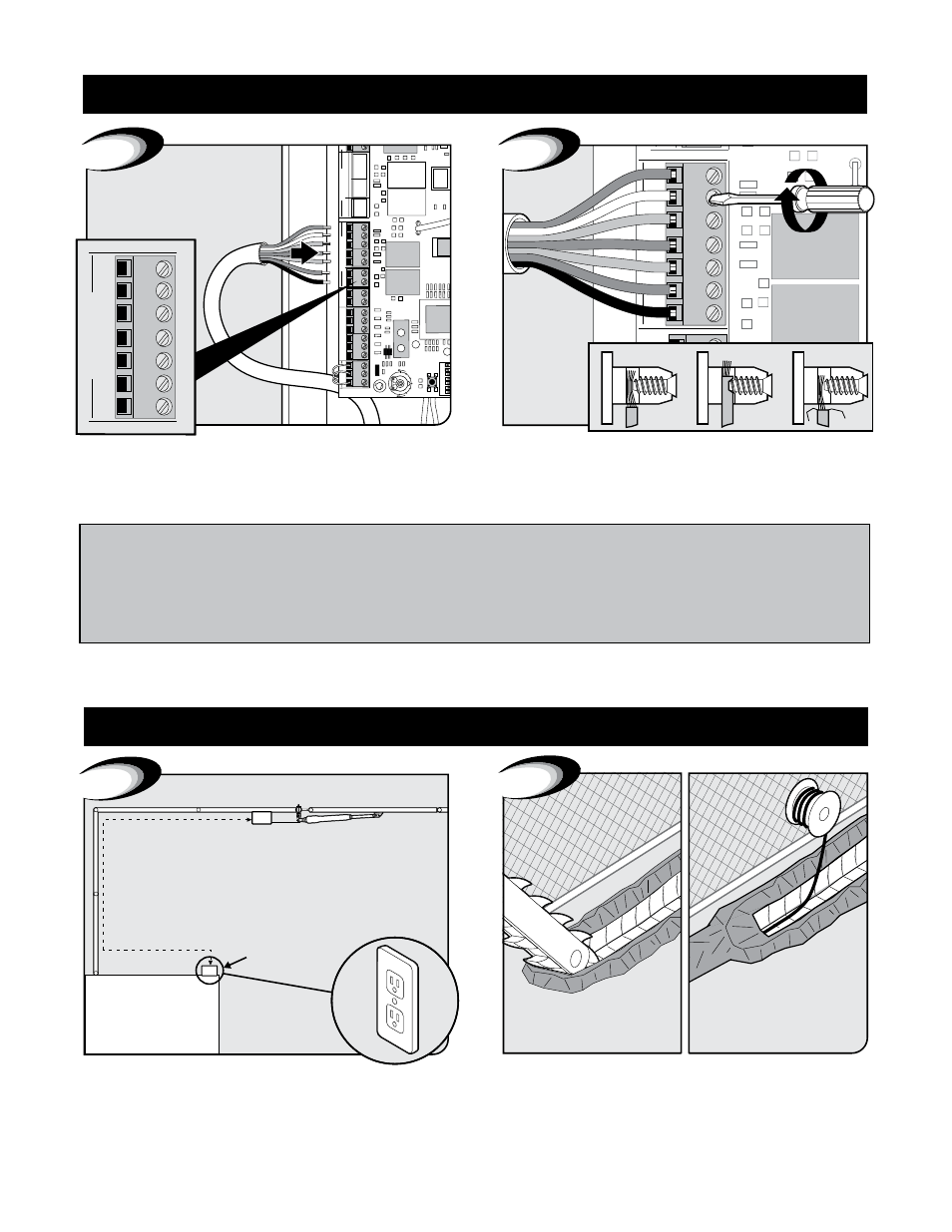
Correct
Wrong
Wrong
8
Secure wires in terminals.
Insert 7 wires into corresponding color terminals.
CAUTION: Please
call your power company
before you dig. Failure to
do so could cause injury
or even death.
10
Top View
Min 3 Ft
Max 1,000 Ft
GTO Transformer
Mounts Here
9
Locate power outlet and identify wire path to control box.
NOTE: If OUTLET is OUTSIDE use weatherproof cover.
Dig trench and lay wire from AC power source to control box.
Use only 16 guage multi-stranded, low voltage, PVC sheathed
wire (RB509). NOTE: DO NOT use telephone wire or solid core
wire. NEVER splice wires together. We recommend running wire
in PVC conduit.
Transformer Wiring Installation
I
f
usIng
optIonal
solar
panel
charger
Instead
of
transformer
,
go
to
page
23.
Important: d
o
not
connect
both
solar
panel
and
transformer
.
Control Box Installation
Control Box Installation