Control box installation, Transformer wiring installation – GTO UL325 SERIES User Manual
Page 24
21
11
C
3
1
1
2
12
13
10”
SW
ITC
H
MASTER INPUTS
GR
N
W
HT
BLU
E
BR
N
OR
G
RED
BLK
CO
M
18V
AC
SOLAR
RELA
Y OUT
SLA
VE INPUTS
GRN
WHT
BL
UE
BRN
ORG
RED
BLK
NC
RL
Y-COM
NO
+
–
~
~
18V
AC
SOLAR
RELA
Y OUT
NC
RL
Y-COM
NO
+
–
~
~
14
18V
AC
SOLAR
RELA
Y OUT
SLA
VE I
NP
UT
S
GR
N
W
HT
BLU
E
BR
N
NC
RL
Y-COM
NO
+
–
~
~
Correct
Wrong
Wrong
15
AC
@5
3>
@=
B3
1B
=@
16
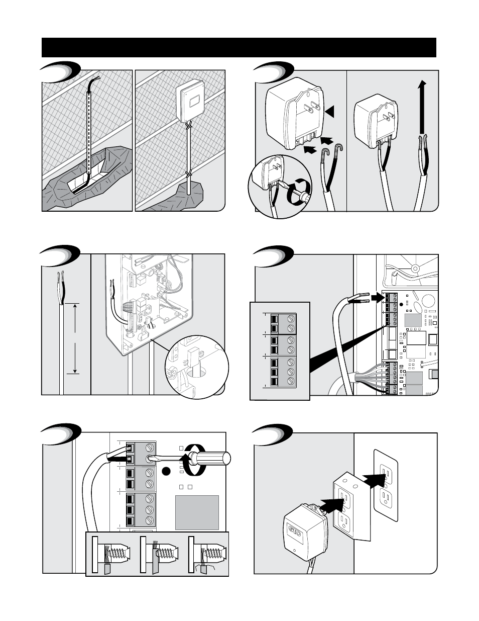
Plug in transformer to power outlet. (Use of a surge protector is
highly recommended. If outdoors use weatherproof box.)
Secure with terminal screws.
Feed other end of low voltage wire 10” into box through
the hole.
Insert one wire into each 18VAC terminal. Colors do not matter.
Cut excess cable/strip 1/2” off 2 wires/twist ends. Attach wires
to transformer screw terminals.
Use PVC conduit from ground up to control box.
Transformer Wiring Installation
Control Box Installation