Installation – Graco Inc. 218-745 User Manual
Page 8
8
307-712
INSTALLATION
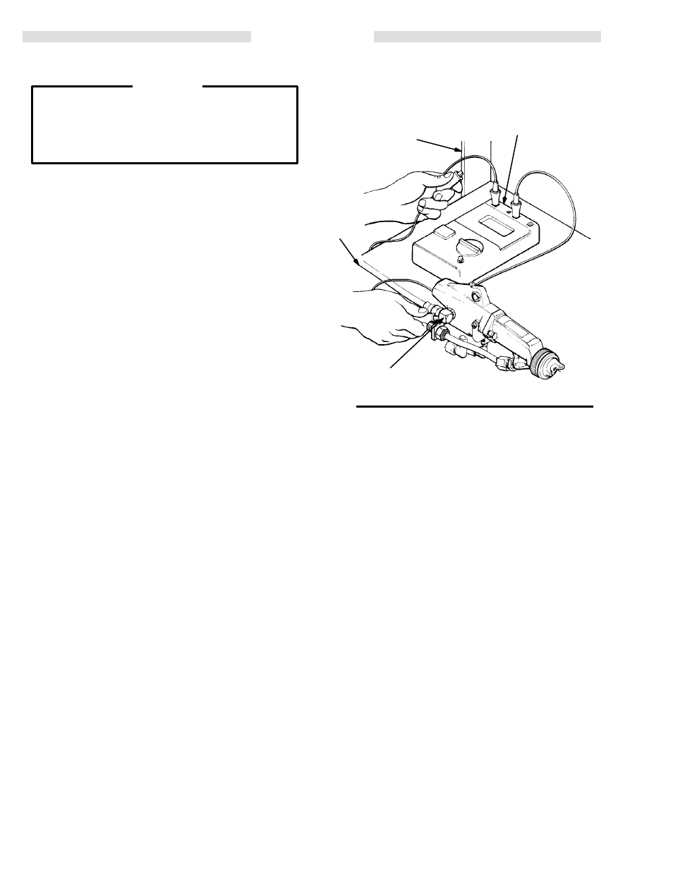
Check the Electrical Grounding
WARNING
Proper electrical grounding of every part of your
system is essential. For your safety, read the warn-
ing section, FIRE OR EXPLOSION HAZARD, on
page 5. Ground the system as explained there.
Then check your system as explained below.
1.
Shut off all air lines to the gun.
2.
Shut off the fluid supply to the gun.
3.
Have a qualified electrician check the electrical
grounding continuity of the spray gun and air hose.
a.
With the electrically conductive air hose (BB)
connected and properly grounded, use a
megohmmeter (AA) (shown in ACCESSORIES
section) to measure the resistance between the
gun body (Y) and a true earth ground (Z). Use an
applied voltage of 500 volts
minimum to 1000
volts
maximum. See Fig 1.
b.
If the resistance is greater than 2 megohms,
check the tightness of the ground connections,
and be sure the air supply hose ground wire is
connected to a true earth ground. If the resis-
tance is still greater than 2 megohms, replace
the air supply hose.
Installing Optional Remote Fan Air Adapter
NOTE: See ACCESSORIES to order the Remote Fan
Air Adapter 181–053 and 90
_
Elbow 108–234.
1.
Place a wrench on the flats of the valve housing (55)
and remove the fan air valve assembly from the gun
body (1). See Fig 20, page 23.
Fig 1
KEY
Y
Turbine Air Inlet
Z
True Earth Ground
AA
Ohmmeter
BB
Grounded Air Hose
Z
Y
AA
BB
2.
Apply PTFE tape to the threads of the remote fan air
adapter (part no. 181–053) and install it in the gun
body (1). Torque the adapter to 1.1–1.4 N
S
m (10–12
in-lb).
3.
Install the 90
_
elbow (part no. 108–234) in the
adapter.
4.
Install the remote fan air line, solenoid valve, air regu-
lator and shut-off valve as instructed in Connect the
Air Lines, on page 7.