Electrical tests, Test resistor stud resistance – Graco Inc. 218-745 User Manual
Page 17
17
307-712
ELECTRICAL TESTS
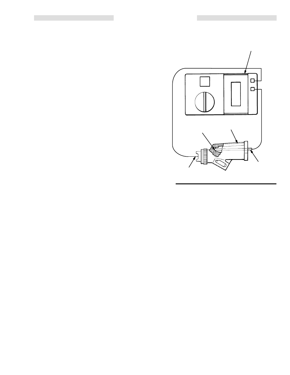
Test Resistor Stud Resistance
Insert a conductive rod (FF) into the gun barrel (removed
for the power supply test) and against the metal contact
(GG) in the front of the barrel. See Fig 9.
Measure the resistance between the conductive rod (FF)
and the gun electrode (14). The resistance should be 20
to 30 megohms. If the resistance is correct, refer to the
Electrical Troubleshooting Chart for other possible
causes of poor performance, or contact the nearest
authorized service agency.
If the resistance is outside the specified range, remove
the electrode (14). See Electrode Replacement. Meas-
ure the resistance between the conductive rod (FF) and
the resistor in the inside diameter of resistor stud (17).
The resistance should be 20 to 30 megohms. If the resis-
tance is correct, the electrode wire is defective and must
be replaced. See Electrode Replacement. If the resis-
tance is outside the specified range, the resistor is defec-
tive and the resistor stud (17) must be replaced. See Re-
sistor Stud Replacement.
If you still have problems, refer to the Electrical
Troubleshooting Chart for other possible causes of
poor performance, or contact the nearest authorized
service agency.
KEY
A
Megohmmeter
FF
Conductive Rod
GG
Metal Contact
14
Electrode
20
Gun Barrel
Fig 9
A
GG
14
20
FF