GarrettCom 6K25 User Manual
Page 64
Magnum 6K25 Managed Fiber Switch Installation and User Guide (04/06)
57
www GarrettCom com
.
.
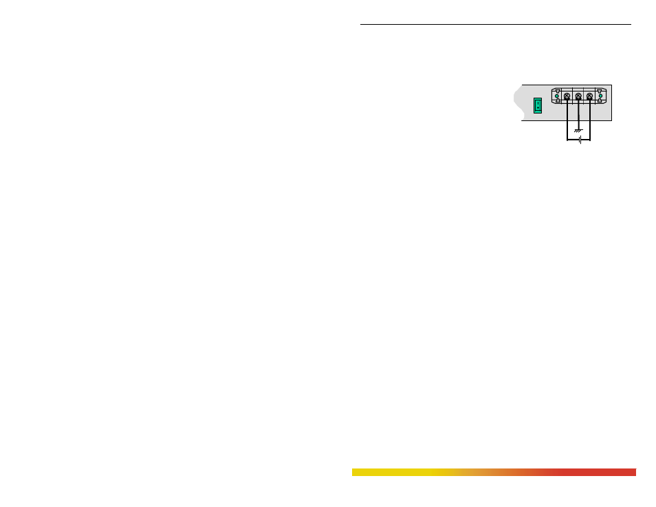
B4.0 INSTALLATION
This section describes the installation of the -48 VDC, 24VDC and 125VDC
power source leads to the -48 VDC, 24VDC and 125VDC power terminal block on the
Magnum 6K25s. (see figure at right).
In this picture, the -48VDC
terminal block on the Magnum 6K25 is
located on the rear of the unit and is
equipped with three (3) screw-down
lead posts. It is similar for 24VDC and
125VDC options on Magnum 6K25.
The leads are identified as negative (-),
positive (+), Figure B4.0: -48VDC Terminal Block on Magnum 6K25-48VDC
and chassis ground (GND).
The actual connection procedure is very straightforward. Simply connect the
leads to the Magnum unit, beginning with ground. Ensure that each lead is securely
tightened.
Note: The GND should be hooked up first. The 6K25 unit has a floating ground, so the
user may elect to Ground either + or = terminal to suit the customer’s use.
Before connecting hot lines to the Terminal Block of –48VDC, 24VDC or
125VDC, always use a digital voltmeter to measure the output voltage of the power
supply and determine the lead which is more “+ve potential”. The more “+ve” voltage
lead from 48V or –48V supply must be connected to the post labeled “+”.
An ON-OFF manual switch is optional for DC power. This can be used to cut
off power connections and as a RESET for the Magnum 6K25 Switch.
B4.1
UL Requirements for DC-powered units
1. Minimum 18AWG cable for connection to a Centralized DC power source.
2. Minimum 14AWG cable for connection to a earthing wiring.
3. Use only with Listed 10 A circuit breaker provided in building installation.
4. “Complies with FDA radiation performance standards, 21 CFR subchapter J.”
or equivalent.
5. Fastening torque of the lugs on the terminal block: 9 inch-pound max.
6. Centralized DC Power Source cable securement, use at least four cable ties to
secure the cable to the rac,k at least 4 inches apart, with the first one located
within 6 inches of the terminal block.
36-70VDC
_
+
GND
ON
OFF