GarrettCom 6K25 User Manual
Page 37
Magnum 6K25 Managed Fiber Switch Installation and User Guide (04/06)
30
www GarrettCom com
.
.
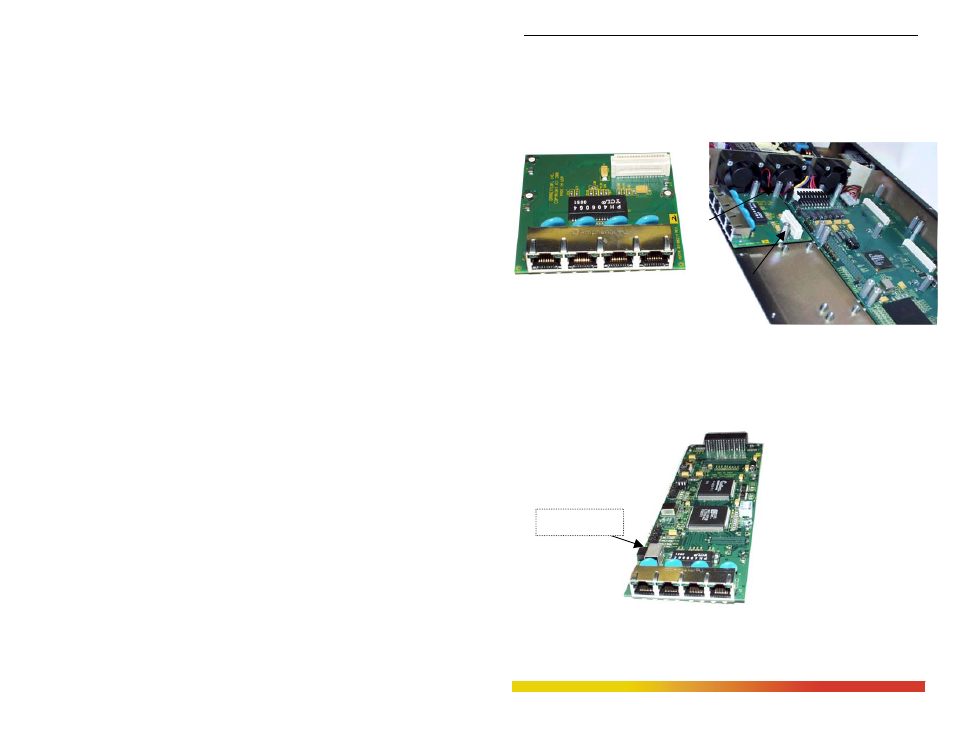
Step 2. Placed Granddaughter board (as shown in fig. 3.5.2a and 3.5.2b) on the chassis
built in stand off (female) provided at the front of the 6K25 Main Board and
screw down tightly with the three 5/16 stand-off (male) on the top of the
Granddaughter board The 5/16 stand off has been used to place the daughter
board on the top of the granddaughter board and latch it securely.
Fig 3.5.2a Granddaughter Board
shown separately
Fig 3.5.2b Granddaughter Board placed in slot
A and secured with three 7/16 stand-off’s
Step 3. The figure here illustrates the basic layout of an individual PM card. Each
6KPM card fits into the space provided on the main board.
Fig. 3.5.2c Daughter Board,
top view of version for 4
copper 10/100 ports. Port# 1
Can be configured as uplink
(x) crossed ports for
cascading
as shown in the Fig.
Uplink