Generac Power Systems Recreational Vehicle Generator 5413 User Manual
Page 53
Section 7
DIAGNOSTIC TESTS
TEST 25 – CHECk FUEL SUPPLY
DISCUSSION (GASOLINE MODELS):
If the engine cranks but won’t start, don’t overlook the
obvious. The fuel supply may be low. Many RV gener-
ator installations “share” the fuel tank with the vehicle
engine. When such is the case, the Installer may have
used a generator fuel pickup tube that is shorter than
the vehicle engine’s pickup tube. Thus, the generator
will run out of gas before the vehicle engine.
PROCEDURE:
Check fuel level in the supply tank. Attach a fresh fuel
supply if necessary and restart. Fuel may be stale,
causing a hard start.
RESULTS:
1. If necessary, replenish fuel supply.
2. If fuel is good, go to Test 26 (for Problem 7,
Section 6).
Go to Test 29 for Problem 8 (Section 6).
DISCUSSION (LPG MODELS):
LP gas is stored in pressure tanks as a liquid. The gas
systems used with these generators were designed
only for vapor withdrawal type systems. Vapor with-
drawal systems use the gas vapors that form above
the liquid fuel in the tank. Do NOT attempt to use the
generator with any liquid withdrawal type system.
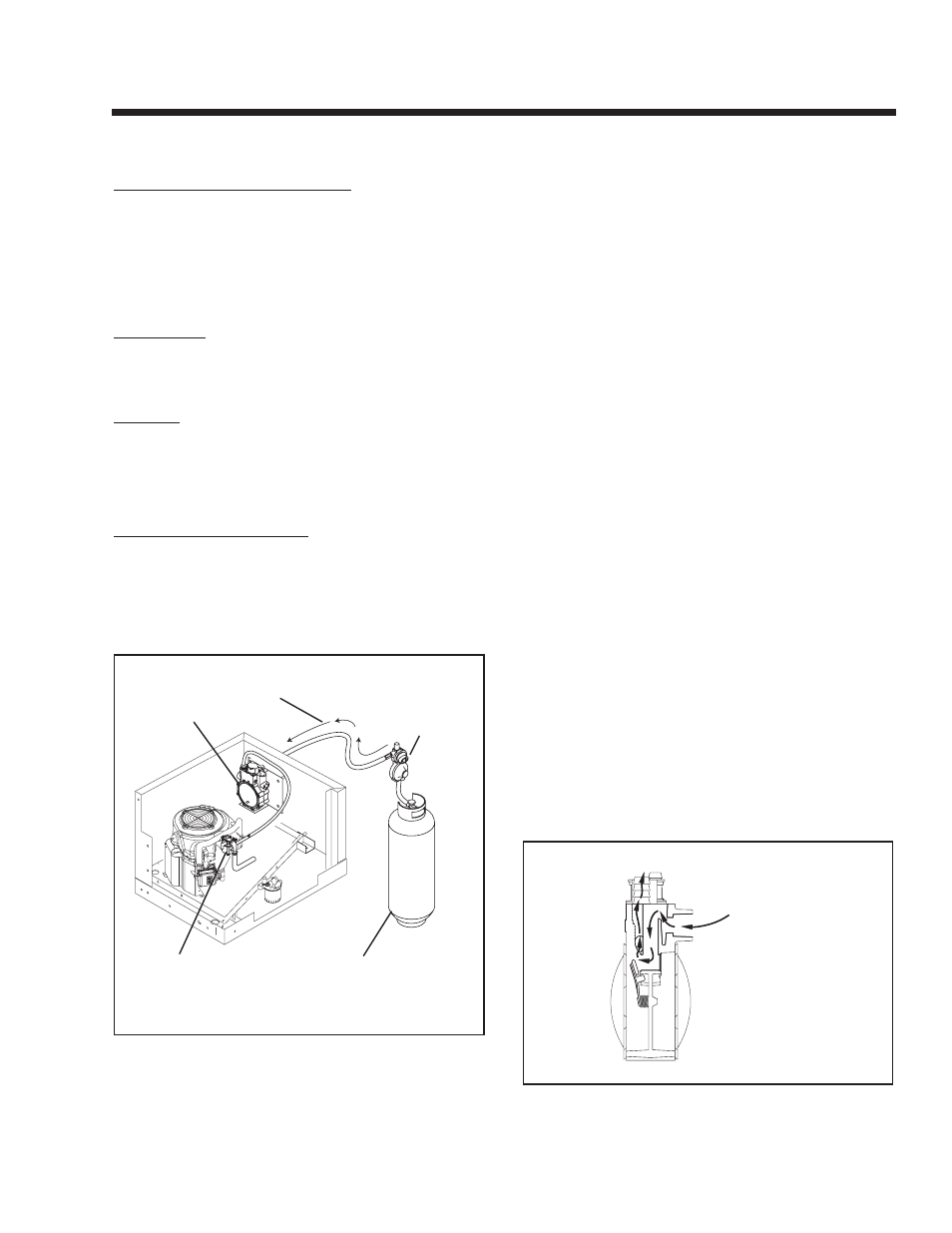
REGULATOR
PRIMARY
REGULATOR
11 - 14" WATER COLUMN
CARBURETOR
VAPOR
WITHDRAWAL
TANk
Figure 7-27 – Typical Propane Gas Fuel System
Gas pressure delivered to the solenoid valve must be
properly regulated by means of a primary gas regula-
tor. Mount the primary regulator at the gas tank outlet
or in the supply line from the gas tank. The following
rules apply:
• For best results, the primary regulator supplies gas-
eous fuel to the secondary regulator at 11 inches
water column. Do NOT exceed 14 inches water col-
umn.
• The installer must be sure the primary regulator is
rated at sufficient gas flow to operate the generator
plus all other gas appliances in the circuit.
NOTE: Recommended MINIMUM gas flow rate for
all air-cooled RV series generators is 67 cubic feet
per hour.
If an existing primary gas regulator does not have
a sufficient flow capacity for the generator and
other gas appliances in the circuit, (a) install a
primary regulator with adequate flow rate, or (b)
install a separate regulator only and rated at least
67 cubic feet per hour. The inlet side of any pri-
mary regulator that supplies the generator must
connect directly to a gas pressure tank. do NOT
tee the generator line into a gas circuit feeding
other areas.
$
CAUTION! Use only approved components in
the fuel supply system. All components must
be properly installed in accordance with appli-
cable codes. Improper installation or use of
unauthorized components may result in fire
or an explosion. Follow approved methods to
test the system for leaks. No leakage is per-
mitted. Do not allow fuel vapors to enter the
vehicle interior.
LP gas vapors should be supplied to the second-
ary regulator inlet at about 11 inches water column
(positive pressure). The engine pistons draw air in
during the intake stroke (Figure 7-28). This air passes
through a carburetor venturi, which creates a low
pressure that is proportional to the quantity of air
being pumped. The low pressure from the carburetor
venturi acts on the regulator diaphragm to pull the
diaphragm toward the source of low pressure. A lever
attached to the diaphragm opens a valve to permit
gas glow through the carburetor.
GAS IN
TO CARBURETOR
Figure 7-28 – LP Gas Carburetion Diagram
Page 51