Generac Power Systems Recreational Vehicle Generator 5413 User Manual
Page 46
Section 7
DIAGNOSTIC TESTS
TEST 14 – TRY CRANkINg THE ENgINE
DISCUSSION:
If the Start-Stop Switch on the generator panel is
actuated, but the Fuel Pump does not run (priming
function doesn’t work), perhaps battery voltage is not
available.
PROCEDURE:
Hold the Start-Stop Switch at “START”. The engine
should crank and start.
RESULTS:
1. If the engine cranks normally, but the priming
function still doesn’t work, go to Test 20.
2. If engine will not crank, go to Test 16. Refer to
Problem 6 of Section 6.
3. If engine cranks but won’t start, go to Problem 7
of Section 6.
4. If engine starts hard and runs rough, go to
Problem 8 of Section 6.
TEST 15 – CHECk FUEL PUMP
DISCUSSION:
An inoperative Fuel Pump will (a) prevent the priming
function from working and (b) prevent the engine from
starting.
PROCEDURE:
1. Remove Fuel Filter and verify that filter is not
clogged. Replace filter if necessary.
2. Verify that fuel is available to Fuel Filter inlet. Use
an alternative fuel supply if questionable.
3. Remove air filter access panel and air filter.
Remove fuel hose from pump. Place a suit-
able container to catch fuel from fuel pump line.
Activate fuel primer switch. Pump should operate
and fuel should flow. If pump does not operate,
proceed to Step 4.
4. This step will test the ground wire. Disconnect
Connector 2 at the Fuel Pump. Set the VOM to
measure resistance. Connect one test lead to
the Black wire, (Pin 2 of Connector 2) that goes
to the Control Panel (see Figure 7-14). Connect
the other test lead to a clean frame ground .
“Continuity” should be measured.
5. To test for an open fuel pump coil, connect one
test lead to the Red Wire (Pin 1 of Connector 2)
going to the fuel pump. Connect the other test lead
to the Black Wire (Pin 2 of Connector 2) going to
the Fuel Pump (see Figure 7-14). The VOM should
indicate Fuel Pump coil resistance of about 29.5
kW. (Current draw of the pump at nominal voltage
is approximately 1.4 amperes MAxIMUM).
Short to Ground:
6. To test for a shorted fuel pump coil, connect one
test lead to the Red Wire (Pin 2 of Connector 2,
see Figure 7-14). Connect the other test lead to
the fuel pump housing. “Infinity” should be mea-
sured.
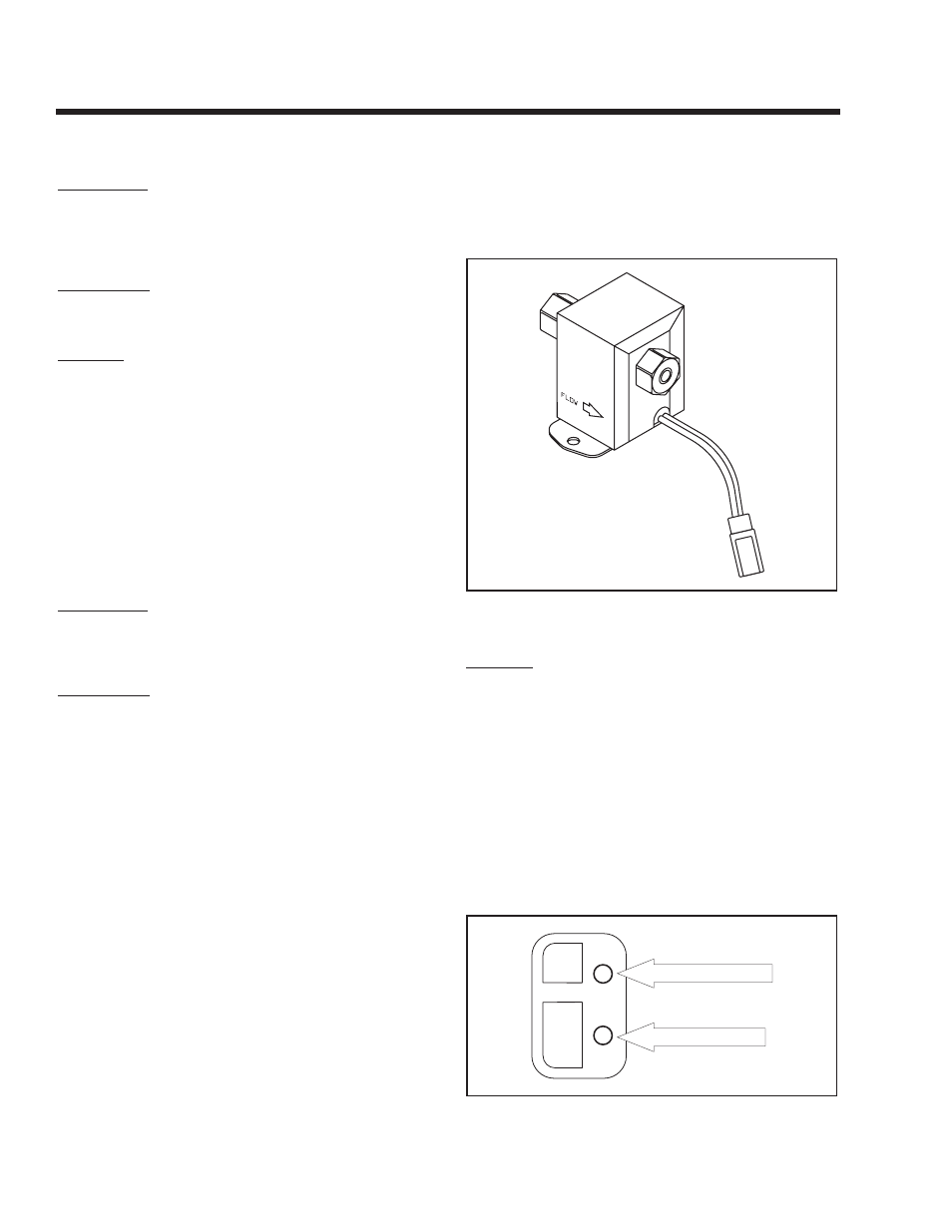
FLOW
Figure 7-13. – Electric Fuel Pump
RESULTS:
1. If “Continuity” was not measured in Step 4, repair
or replace Wire 0 between Connector 2 and the
ground terminal.
2. If “Continuity” is measured in Step 4, but pump
does not operate in Step 3, replace the Fuel
Pump.
3. If the pump fails Step 5 or Step 6, replace the
Fuel Pump.
Note: If desired, a pressure gauge can be attached
to the pumps outlet side. Pump outlet pressure
should be 2.0 to 3.5 psi.
4. If the pump operates normally, go to Test 28.
PIN 1 - RED WIRE
PIN 2 - BLACk WIRE
Figure 7-14. – Harness to Fuel Pump
Page 44