Test 19 – check continuity of wire 17, Test 20 – check start-stop switch – Generac Power Systems Recreational Vehicle Generator 5413 User Manual
Page 48
TEST 19 – CHECk CONTINUITY OF WIRE 17
DISCUSSION:
A faulty condition in Wire 17 could prevent the unit
from cranking when the Start-Stop switch is held in
the “Start” position.
PROCEDURE:
1. Disconnect Wire 17 from its Switch terminal and
connect it to frame ground. The engine should
crank. If unit cranks, proceed to Step 2. If unit
does not crank when grounding Wire 17, go back
to Test 18 “Check Power Supply to Printed Circuit
Board”, then repeat Step 1. If unit cranks, proceed
to Test 20.
2. With Wire 17 still disconnected from SW1, discon-
nect the j1 Connector from the PCB.
3. Set a VOM to its “Rx1” scale and zero the meter.
4. Connect one meter test lead to each end of Wire
17.
5. “Continuity” should be measured.
RESULTS:
1. If “Continuity” is not measured in Step 5, repair or
replace Wire 17.
2. If “Continuity” is measured in Step 5, replace PCB.
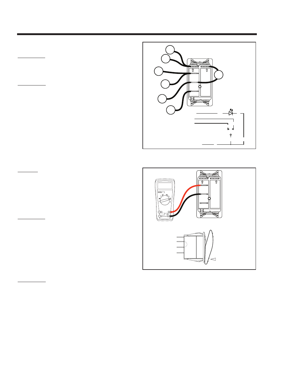
TEST 20 – CHECk START-STOP SWITCH
DISCUSSION:
Engine cranking and startup is initiated when Wire
17 from the Printed Circuit Board (PCB) is connected
to frame ground by setting the Start-Stop Switch to
“START”.
Engine shutdown occurs when Wire 18 from the
PCB is connected to frame ground by the Start-Stop
Switch.
A defective Start-Stop Switch can result in (a) failure
to crank when the switch is set to “START”, and/or (b)
failure to shut down when the switch is set to “STOP”.
PROCEDURE:
Refer to Problem 6 (Section 6).
1. Set a VOM to its “Rx1” scale and zero the meter.
2. Remove the 7.5 amp fuse. Disconnect all wires
from Start-Stop Switch (SW1).
3. Inspect the ground Wire 0, between the Start-
Stop Switch and the grounding terminal. Connect
one meter test lead to Wire 0 on SW1. Connect
the other test lead to a clean frame ground.
“Continuity” should be measured.
SW1
START
PRIME
STOP
18
17
0
LED
0
712
0
0
8
1
2
3
7
4
5
6
712
712
18
18
17
0
0
JUMPER WIRE
Figure 7-16. – Start-Stop Switch
CONTINUITY
DEPRESSED
AWAY FROM
TERMINAL BEING
TESTED
8
1
2
3
7
4
5
6
0000
Figure 7-17. – Test 20, Step 5
5. Connect one test lead to the Terminal 1 of SW1
(see Figure 7-17). Connect the other test lead to
Terminal 2 of SW1. “Continuity” should be mea-
sured.
6. Connect one test lead to the Terminal 2 of SW1
(see Figure 7-18). Connect the other test lead to
Terminal 3 of SW1. “Continuity” should be mea-
sured.
Page 46
Section 7
DIAGNOSTIC TESTS