Generac Power Systems Recreational Vehicle Generator 5413 User Manual
Page 12
Section 2
MAJOR GENERATOR COMPONENTS
NOTE: If, for any reason, sensing voltage to the
regulator is lost, the regulator will shut down and
excitation output to the Rotor will be lost. The
AC output voltage will then drop to a value that
is commensurate with Rotor residual magnetism
(about 7-12 VAC). Without this automatic shut-
down feature, loss of sensing (actual) voltage to
the regulator would result in a “full field” or “full
excitation” condition and an extremely high AC
output voltage.
NOTE: Adjustment of the regulator’s “VOLTAgE
AdJUST” potentiometer must be done only when
the unit is running at its correct governed no-load
speed. Speed is correct when the unit’s no-load
AC output frequency is about 60.0-60.5 Hertz. At
the stated frequency, AC output voltage should be
about 124 volts.
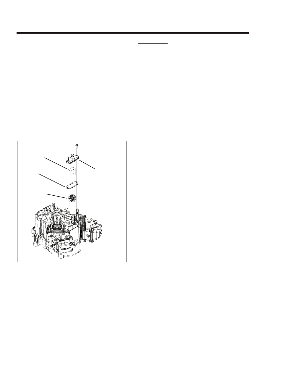
CRANkCASE BREATHER
CRANKCASE
BREATHER
GASKET
SCREEN
OIL VAPOR
COLLECTOR
Figure 2-8. – Crankcase Breather
DESCRIPTION:
The crankcase breather is equipped with a reed valve
to control and maintain a partial vacuum in the crank-
case. The breather is vented to the airbox. The breath-
er chamber contains a removable oil vapor collector.
Oil vapor is condensed on the collector material and
drains back into the crankcase, which minimizes the
amount of oil vapor entering the breather.
CHECk BREATHER:
1. Disconnect breather tube and remove two screws
and breather. Discard gasket.
2. Remove oil vapor collector and retainer.
3. Check collector for deterioration and replace if
necessary.
INSTALL BREATHER:
1. Install oil vapor collector and retainer.
Note: Push oil vapor collector and retainer in until
it bottoms.
2. Install breather with new gasket (Figure 2-8).
a. Torque screws to 5-8 ft-lbs.
3. Assemble breather tube to intake elbow.
Page 10