Page 19 – Generac Power Systems Recreational Vehicle Generator 5413 User Manual
Page 21
Section 5
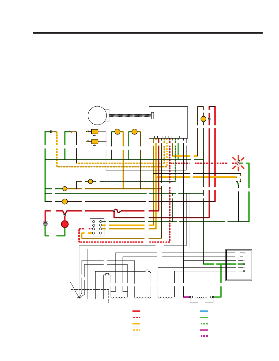
ENGINE DC CONTROL SYSTEM
Page 19
SC - STARTER CONTACTOR
TB - TERMINAL BLOCK, 4 TAB
SP2 - SPARK PLUG, CYL. 2
SP1 - SPARK PLUG, CYL. 1
LED - ALARM INDICATOR
LOP - LOW OIL PRESSURE SWITCH
SCR - STARTER CONTACTOR RELAY
SM - STARTER MOTOR
SW1 - PRIME/START-RUN-OFF SWITCH
FS - FUEL SOLENOID
FP - FUEL PUMP
F1 - FUSE, 7.5A
CH - CHOKE HEATER
CS - CHOKE SOLENOID
IMS - IGNITION MODULE STUD
IM2 - IGNITION MODULE, CYL. 2
HTO - HIGH OIL TEMPERATURE SWITCH
IM1 - IGNITION MODULE, CYL. 1
GRD1 - CONTROL PANEL GROUND
GRD2 - UNIT GROUND STUD
BA - BRUSH ASSEMBLY
CB 1 / CB 2 - SEE CHART
LEGEND
= 12 VOLTS DC
= ALARM CONTROL (PCB)
= DC CONTROL VOLTAGE (PCB)
= SHUTDOWN CONTROL (PCB)
= GROUND
= GROUND CONTROL (PCB)
= FIELD BOOST
= VOLTAGE REGULATOR
DC OUTPUT
= AC VOLTAGE
IM1
IM2
SP1
SP2
12
J1
1 2 3 4 5 6 7 8
10
9
11
13 14
PRINTED CIRCUIT BOARD
J2
CONTROL
ACTUATOR
GOVERNOR
SW1
START
PRIME
STOP
18
17
0
SCR
56
16
F1
0
13
16
56
FP
LOP
HTO
BLK
RED
18A
0
86
0
85
REGULATOR
VOLTAGE
2
2
0
6
22S
4
11S
6
0
4
22S
11S
LED
0
712
CH
CS
0
90
14
RED
BLACK
SM
SC
BATTERY
+
-
12V
SC
0
0
16
16
0
13
POWER WINDINGS
11
BA
33
DPE WINDING
6
2
4
0
44
CB2
CB1
FIELD
BLACK
RED
18
17
0
56
712
0
18
11S
22S
13
16
0
17
REMOTE
PANEL
CONNECTOR
14
712
D
E
G
F
C
B
18
17
H
A
0
GREEN
WHITE
0
13
712
14
0
GREEN
WHITE
0
NEUTRAL CONNECTION
AC CONNECTION
CUSTOMER
BY CUSTOMER
18
15
17
712
86
90
14
85
56
0
18A
4
15
11S
0
14
0
241
FS
14
712
22
44
44
22
22S 22
0
0
0
+
-
CIRCUIT CONDITION – CRANkING:
When the START-STOP SWITCH (SW1) or REMOTE PANEL START
SWITCH is momentarily held in the “START” position and then
released, Wire 17 from the Printed Circuit Board (PCB ) is connected
to frame Ground. PCB action will then deliver battery voltage to a
STARTER CONTACTOR RELAY (SCR) via Wire 56, and to an auto-
matic CHOkE SOLENOID (CS) via Wire 14.
When battery voltage energizes the STARTER CONTACTOR RELAY
(SCR), it’s contacts close and battery output is delivered to the
STARTER CONTACTOR (SC) via Wire 16. When the STARTER
CONTACTOR (SC) energizes, it’s contacts close, and battery out-
put is delivered to the STARTER MOTOR (SM) via Wire 16. The
STARTER MOTOR energizes and the engine cranks.
When the STARTER CONTACTOR RELAY (SCR) closes, battery
voltage is also delivered to PCB Pin 13 . This voltage is reduced for
use as field boost and is output from PCB Pin 13 to the rotor. While
cranking, the CHOkE SOLENOID (CS) is energized by grounding
Wire 90 cyclically by PCB action (two seconds on, two seconds off).
Also while cranking, PCB action energizes Pin 5, and delivers battery
voltage to the Wire 14 circuit. This energizes the FUEL PUMP (FP)
via a Red wire, FUEL SOLENOID (FS) via Wire 241 and CHOkE
HEATER (CH) via Wire 14. Battery voltage is also delivered to an
optional light or hour meter in the Remote Panel, if equipped.
PCB action now holds open Wire 18A to common ground, and the
Magneto will induce a spark during cranking.