Generac Power Systems Recreational Vehicle Generator 5413 User Manual
Page 38
Section 7
DIAGNOSTIC TESTS
INTROdUCTION
The “Diagnostic Tests” in this chapter may be per-
formed in conjunction with the “Flow Charts” of
Section 6. Test numbers in this chapter correspond to
the numbered tests in the “Flow Charts”.
Tests 1 through 13 are procedures involving problems
with the generator’s AC output voltage and frequency
(Problems 1 through 3 in the “Flow Charts”).
Tests 14 through 41 are procedures involving prob-
lems with engine operation (Problems 3 through 10 in
the “Troubleshooting Flow Charts”).
You may wish to read Section 4, “Measuring
Electricity”.
NOTE: Test procedures in this Manual are not nec-
essarily the only acceptable methods for diagnos-
ing the condition of components and circuits. All
possible methods that might be used for system
diagnosis have not been evaluated. If you use
any diagnostic method other than the method
presented in this Manual, you must ensure that
neither your safety nor the product’s safety will be
endangered by the procedure or method you have
selected.
TEST 1 – CHECk NO-LOAd VOLTAgE ANd
FREqUENCY
DISCUSSION:
The first step in analyzing any problem with the AC
generator is to determine the unit’s AC output volt-
age and frequency. Once that has been done, you will
know how to proceed with specific diagnostic tests.
PROCEDURE:
1. Set a volt-ohm-milliammeter (VOM) to read AC
voltage. Connect the meter test leads across cus-
tomer connection leads T1 (Red) and T2 (White).
2. Disconnect or turn OFF all electrical loads. Initial
checks and adjustments are accomplished at no-
load.
3. Start the engine, let it stabilize and warm up.
4. Read the AC voltage.
5. Connect an AC frequency meter across AC output
leads T1 (Red) and T2 (White). Repeat the above
procedure.
RESULTS:
For units rated 60 Hertz, no-load voltage and fre-
quency should be approximately 122-126 VAC and
60.0-60.5 Hertz respectively.
1. If AC voltage and frequency are BOTH corre-
spondingly high or low, go to Test 2.
2. If AC frequency is good but low or residual volt-
age is indicated, go to Test 4.
3. If AC output voltage and frequency are both “zero”,
go to Test 11.
4. If the no-load voltage and frequency are within the
stated limits, go to Test 12.
NOTE: The term “low voltage” refers to any voltage
reading that is lower than the unit’s rated voltage.
The term “residual voltage” refers to the output
voltage supplied as a result of Rotor residual
magnetism (approximately 5-12 VAC).
TEST 2 – CHECk STEPPER MOTOR CONTROL
*
Caution! Do not stand in front of carburetor
when checking the stepper motor movement
due to possible backfire from the carburetor.
PROCEDURE:
1. Remove air cleaner cover to access stepper
motor.
2. Physically grab the throttle and verify the stepper
motor, linkage and throttle do not bind in any way.
If any binding is felt, repair or replace components
as needed. Some resistance should be felt as the
stepper motor moves through it’s travel.
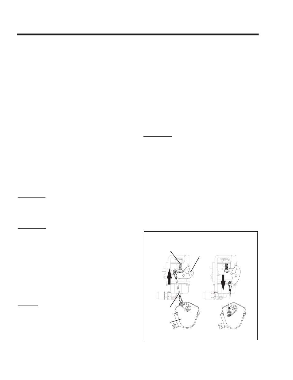
3. Physically move the throttle to the closed position
by pulling the stepper motor arm towards the idle
stop.
a. Press the Start-Stop switch (SW1) to “START”
and watch for stepper motor movement. It should
move to the wide open (down) position during
cranking. Once the unit starts the stepper motor
should move the throttle to a position to maintain
60.0-60.5 Hertz.
THROTTLE
ARM
IDLE
STOP
UP
CLOSED
DOWN
OPEN
THROTTLE
LINKAGE
STEPPER
MOTOR
Figure 7-1. Throttle Position
Page 36