Generac Power Systems Recreational Vehicle Generator 5413 User Manual
Page 45
Section 7
DIAGNOSTIC TESTS
POSITIVE (+)
TEST LEAD
Figure 7-11. – Rotor Assembly
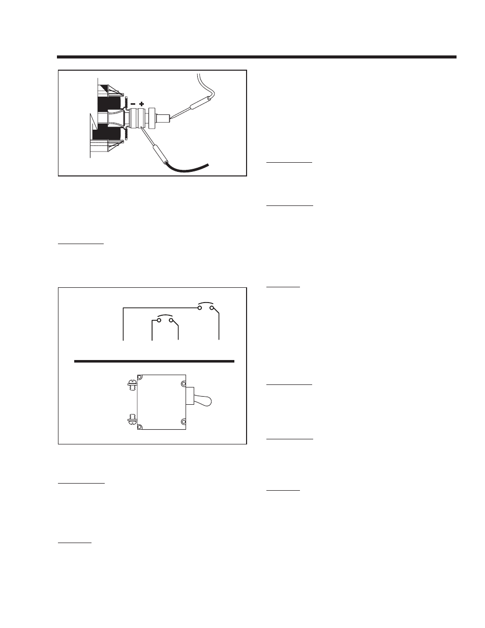
TEST 11 – CHECk MAIN CIRCUIT BREAkER
DISCUSSION:
The main circuit breaker on the generator panel must
be closed or no output to the load will be available.
A defective breaker may not be able to pass current
even though it is in the “ON” position.
CB2
CB1
33
11
BLACk
SCHEMATIC
PICTORIAL
RED
Figure 7-12. – Main Breaker (Typical)
PROCEDURE:
Set the coach main breaker to it’s “OFF” position.
Check that the appropriate main breaker on the gen-
erator panel is set to its “ON” (closed) position. Set a
VOM to measure resistance and use it to check for
continuity across the breaker terminals.
RESULTS:
1. If breaker is “ON” and “Continuity” is measured,
go to Test 3.
2. If breaker is “OFF”, reset to the “ON” position and
check for AC output.
3. If breaker is “ON” and “Continuity” is not mea-
sured, replace the defective circuit breaker.
TEST 12 – CHECk LOAd VOLTAgE &
FREqUENCY
DISCUSSION:
If engine speed appears to drop off excessively when
electrical loads are applied to the generator, the load
voltage and frequency should be checked.
PROCEDURE:
Perform this test in the same manner as Test 1, but
apply a load to the generator equal to its rated capac-
ity. With load applied check voltage and frequency.
Frequency should not drop below about 60 Hertz with
the load applied.
Voltage should not drop below about 120 VAC with
load applied.
RESULTS:
1. If voltage and/or frequency drop excessively when
the load is applied, go to Test 13.
2. If load voltage and frequency are within limits, end
tests.
TEST 13 – CHECk LOAd WATTS &
AMPERAgE
DISCUSSION:
This test will determine if the generator’s rated watt-
age/amperage capacity has been exceeded.
Continuous electrical loading should not be greater
than the unit’s rated capacity.
PROCEDURE:
Add up the wattages or amperages of all loads pow-
ered by the generator at one time. If desired, a clamp-
on ammeter may be used to measure current flow.
See “Measuring Current” on Page 16.
RESULTS:
1. If the unit is overloaded, reduce the load.
2. If load is within limits, but frequency and voltage
still drop excessively, complete Test 2, “Check
Stepper Motor Control”. If stepper motor adjust-
ment does not correct the problem, go to Problem
8 (Flow Chart, Pages 32 and 33).
Page 43