Generac Power Systems Recreational Vehicle Generator 5413 User Manual
Page 47
Page 45
Section 7
DIAGNOSTIC TESTS
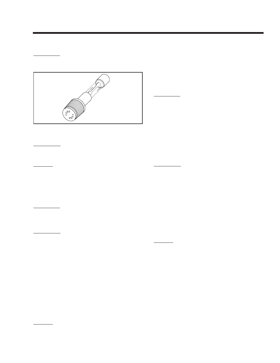
TEST 16 – CHECk 7.5 AMP FUSE
DISCUSSION:
If the panel-mounted 7.5 amp fuse (F1) has blown,
engine cranking will not be possible.
Figure 7-15. – 7.5 Amp Fuse
PROCEDURE:
Push In on fuse holder cap and turn counterclockwise.
Then, remove the cap with fuse. Inspect the Fuse.
RESULTS:
If the Fuse element has melted open, replace the
Fuse with an identical size fuse. If Fuse is good, go to
Test 17.
TEST 17 – CHECk BATTERY & CABLES
DISCUSSION:
If the engine won’t crank or cranks too slowly, the
battery may be weak or discharged. See “Battery” on
Page 22.
PROCEDURE:
1. Inspect the battery cables and battery posts or
terminals for corrosion or tightness. Measure
the voltage at the terminal of the starter contac-
tor and verify 11-12 volts DC is available to the
generator during cranking. If voltage is below 11
volts DC, measure at the battery terminals dur-
ing cranking. If battery voltage is below 11 volts
DC, recharge/replace battery. If battery voltage is
above 11 volts DC, check for proper battery cable
sizing (see “BATTERY CABLES” on Page 24). If
battery or cables are still suspected, connect an
alternate battery and cables to the generator and
retest.
2. Use a battery hydrometer to test the battery for
(a) state of charge and (b) condition. Follow the
hydrometer manufacturer’s instructions carefully.
RESULTS:
1. Clean battery posts and cables as necessary.
Make sure battery cables are tight.
2. Recharge the battery, if necessary.
3. Replace the battery, if necessary.
4. If battery is good, but engine will not crank, go to
Test 18.
TEST 18 – CHECk POWER SUPPLY TO
PRINTEd CIRCUIT BOARd
DISCUSSION:
If battery voltage is not available to the Printed Circuit
Board (PCB), engine cranking and running will not be
possible.
If battery voltage is available to the PCB, but no DC
output is delivered to the board’s Wire 56 terminal
while attempting to crank, either the Printed Circuit
Board is defective or the Start-Stop Switch has failed.
This test will determine if battery voltage is available
to the Printed Circuit Board. Test 20 will check the
Start-Stop Switch. Test 21 will check the DC power
supply to the Printed Circuit Board’s Wire 56 terminal
(j1 Connector, Pin 9).
PROCEDURE:
1. Disconnect j1 Connector from the PCB.
2. On the harness end of the j1 Connector, locate
j1, Pin 4 (Wire 15) (see Figure 5-3 on Page 22).
3. Set a VOM to read battery voltage. Connect the
meter test leads across Printed Circuit Board
Terminal j1, Pin 4 and frame ground. The meter
should read battery voltage.
4. Set the VOM to measure resistance (“Rx1” scale).
Connect one meter test lead to Wire 0, Pin loca-
tion j1-11 on the Printed Circuit Board. Connect
the other test lead to a clean frame ground.
“Continuity” should be measured.
RESULTS:
1. If battery voltage is NOT indicated in Step 3,
check continuity of:
a. Wire 13 between Starter Contactor and
Starter Contactor Relay.
b. Wire 13 between Starter Contactor Relay and
7.5 Amp Fuse (F1).
c. Wire 15 to Wire 13 on the 7.5 Amp fuse hold-
er (F1).
Repair, reconnect or Replace bad wiring as nec-
essary.
2. If battery voltage is indicated but engine will not
crank, go to Test 20.
3. If “Continuity” was not measured in Step 4, repair
or replace Wire 0 between the Printed Circuit
Board and the Ground Terminal.