Test 21 – check power supply to wire 56, Test 22 – check starter contactor relay – Generac Power Systems Recreational Vehicle Generator 5413 User Manual
Page 49
Section 7
DIAGNOSTIC TESTS
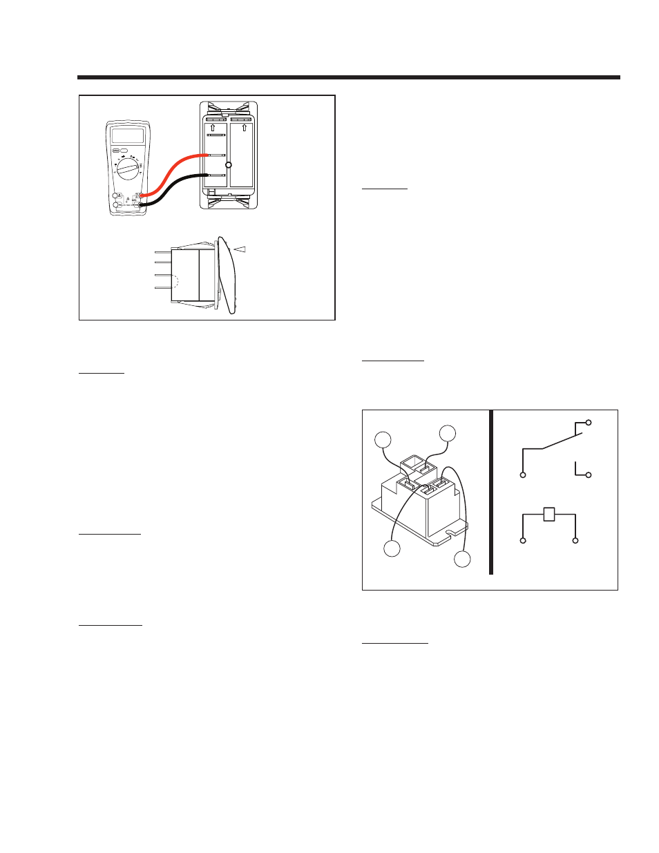
CONTINUITY
DEPRESSED
AWAY FROM
TERMINAL BEING
TESTED
8
1
2
3
7
4
5
6
0000
Figure 7-18. – Test 20, Step 6
RESULTS:
1. If “Continuity” is not measured in Step 3, repair,
reconnect or replace Wire 0 (between Start-Stop
Switch and ground terminal) as necessary.
2. If the Start-Stop Switch (SW1) failed any part of
Steps 2 or 3, replace the switch.
5. If switch tests GOOD, go to Test 21.
TEST 21 – CHECk POWER SUPPLY TO
WIRE 56
DISCUSSION:
If battery voltage is available to the Printed Circuit
Board in Test 18, then DC voltage should be deliv-
ered to Wire 56 when the Start-Stop Switch is set to
“START” (Test 20). This test will check to see if the
Printed Circuit Board is delivering battery voltage to
the Wire 56 terminal.
PROCEDURE:
1. Set a VOM to measure DC voltage (12 VDC).
2. Disconnect Wire 56 from its Starter Contactor
Relay terminal.
3. Connect the meter positive (+) test lead to the
disconnected end of Wire 56. Connect the other
test lead to frame ground. No voltage should be
indicated.
4. Actuate the Start-Stop Switch to its “START” posi-
tion. The meter should indicate battery voltage. If
battery voltage is present, stop the procedure.
5. Connect the VOM positive (+) test lead to Wire 56
(Pin Location j1-9) at the Printed Circuit Board.
Connect the other test lead to frame ground.
6. Actuate the Start-Stop Switch to the “START”
position. The meter should indicate battery volt-
age.
RESULTS:
1. If battery voltage was measured in Step 6, but not
in Step 4, repair or replace Wire 56 between the
Printed Circuit Board and Starter Contactor Relay.
2. If battery voltage was not available in Step 6,
replace the Printed Circuit Board.
3. If battery voltage is available in Step 4 but engine
does not crank, go to Test 22.
TEST 22 – CHECk STARTER CONTACTOR
RELAY
DISCUSSION:
If battery voltage is available to Wire 56 but the engine
won’t crank, the possible cause could be a failed
Starter Contactor Relay.
COM
NO
16
13
56
0
13
16
0
56
Figure 7-19. – Starter Contactor Relay
PROCEDURE:
1. Set the VOM to measure resistance (“R x 1”
scale). Remove Wire 0 from the Starter Contactor
Relay (SCR). Connect one meter test lead to
Wire 0, and connect the other meter test lead to
frame ground. “Continuity” should be measured.
Reconnect Wire 0.
2. Set the VOM to measure resistance (“R x 1”
scale). Disconnect Wire 16 and Wire 13 (Wire 13
is 12 VDC isolate from ground) from the Starter
Contactor Relay (SCR). Connect one meter test
lead to an SCR terminal, and connect the other
meter test lead to the remaining SCR terminal.
Page 47