Page 21 – Generac Power Systems Recreational Vehicle Generator 5413 User Manual
Page 23
Section 5
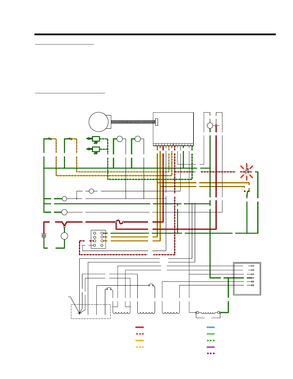
ENGINE DC CONTROL SYSTEM
Page 21
5 Flashes = Low Oil Pressure
4 Flashes = Overspeed
3 Flashes = Overcrank
2 Flashes = Low Battery
6 Flashes = High Oil Temperature
SC - STARTER CONTACTOR
TB - TERMINAL BLOCK, 4 TAB
SP2 - SPARK PLUG, CYL. 2
SP1 - SPARK PLUG, CYL. 1
LED - ALARM INDICATOR
LOP - LOW OIL PRESSURE SWITCH
SCR - STARTER CONTACTOR RELAY
SM - STARTER MOTOR
SW1 - PRIME/START-RUN-OFF SWITCH
FS - FUEL SOLENOID
FP - FUEL PUMP
F1 - FUSE, 7.5A
CH - CHOKE HEATER
CS - CHOKE SOLENOID
IMS - IGNITION MODULE STUD
IM2 - IGNITION MODULE, CYL. 2
HTO - HIGH OIL TEMPERATURE SWITCH
IM1 - IGNITION MODULE, CYL. 1
GRD1 - CONTROL PANEL GROUND
GRD2 - UNIT GROUND STUD
BA - BRUSH ASSEMBLY
CB 1 / CB 2 - SEE CHART
LEGEND
= 12 VOLTS DC
= ALARM CONTROL (PCB)
= DC CONTROL VOLTAGE (PCB)
= SHUTDOWN CONTROL (PCB)
= GROUND
= GROUND CONTROL (PCB)
= FIELD BOOST
= VOLTAGE REGULATOR
DC OUTPUT
= AC VOLTAGE
IM1
IM2
SP1
SP2
12
J1
1 2 3 4 5 6 7 8
10
9
11
13 14
PRINTED CIRCUIT BOARD
J2
CONTROL
ACTUATOR
GOVERNOR
SW1
START
PRIME
STOP
18
17
0
SCR
56
16
F1
0
13
16
56
FP
LOP
HTO
BLK
RED
18A
0
86
0
85
REGULATOR
VOLTAGE
2
2
0
6
22S
4
11S
6
0
4
22S
11S
LED
0
712
CH
CS
0
90
14
RED
BLACK
SM
SC
BATTERY
+
-
12V
SC
0
0
16
16
0
13
POWER WINDINGS
11
BA
33
DPE WINDING
6
2
4
0
44
CB2
CB1
FIELD
BLACK
RED
18
17
0
56
712
0
18
11S
22S
13
16
0
17
REMOTE
PANEL
CONNECTOR
14
712
D
E
G
F
C
B
18
17
H
A
0
GREEN
WHITE
0
13
712
14
0
GREEN
WHITE
0
NEUTRAL CONNECTION
AC CONNECTION
CUSTOMER
BY CUSTOMER
18
15
17
712
86
90
14
85
56
0
18A
4
15
11S
0
14
0
241
FS
14
712
22
44
44
22
22S 22
0
0
0
+
-
CIRCUIT CONDITION – SHUTDOWN:
Setting the START-STOP SWITCH (SW1) or the REMOTE PANEL
START-STOP SWITCH to its “STOP” position connects the Wire
18 circuit to frame ground. Printed Circuit Board action then closes
the circuit to Wire 18A, grounding the ignition magneto. PCB action
de-energizes DC output to j1 plug to the FUEL PUMP (FP), FUEL
SOLENOID (FS) and CHOkE HEATER (CH) are de-energized by the
loss of DC to Wire 14. Ignition and fuel flow are terminated, and the
engine shuts down.
CIRCUIT CONDITION – FAULT SHUTDOWN:
The engine mounts a HIGH OIL TEMPERATURE SWITCH (HTO)
and a LOW OIL PRESSURE SWITCH (LOP).
Should engine oil temperature exceed a preset value, the switch con-
tacts will close. Wire 85 from the Printed Circuit Board will connect to
frame ground. PCB action will then initiate a shutdown and will cause
the red led light on SW1 to flash 6 times then repeat.
Should engine oil pressure drop below a safe pre-set value, the LOP
switch contacts will close. On contact closure, Wire 86 will be connect-
ed to frame ground and PCB action will initiate an engine shutdown
and will cause the red led light on SW1 to flash 5 times then repeat.
The PCB has a built-in time delay for the Wire 85 fault shutdown. At
STARTUP ONLY the circuit board will wait approximately 6 seconds
before looking at the Wire 85 fault shutdowns. Once running, after
the 6 second time delay, grounding Wire 85 through either switch will
cause an immediate shutdown.