Table tilt – Grizzly G0636X User Manual
Page 33
G0636X 17" Ultimate Bandsaw
-31-
2. Slide the bandsaw fence out of the way and
cut halfway through the board on the line by
pushing it into the blade. Turn the bandsaw
OFF and wait for the blade to stop.
3. Clamp the board to the bandsaw table with-
out moving it. Now slide the fence over to
the board so it barely touches one end of the
board.
4. Loosen the two cap screws that secure the
fence rail to the underside of the table (see
Page 26).
5. Skew the fence so it is parallel to the edge of
the scrap piece.
6. While maintaining the skew, tighten the cap
screws loosened in
Step 4.
7.
Make a few cuts using the fence. If the fence
still does not seem parallel to the blade,
repeat
Steps 1–6 until the blade and fence
are parallel with each other.
To shift the table:
1. On a scrap piece of wood, mark a line that is
perpendicular to the front edge.
2. Cut halfway through the board on the line by
pushing it into the blade.
3. Turn the bandsaw OFF and wait for the blade
to stop.
4. Using an 8mm hex wrench, loosen the four
cap screws that mount the table to the trun-
nion (
Figure 31). Shift the table to compen-
sate for the blade lead, then retighten the cap
screws.
5. Repeat Steps 1–4 until the blade cuts
straight.
Personal injury or death
can occur if the bandsaw
starts during table adjust-
ment. Disconnect power
from the bandsaw before
performing table adjust-
ments.
The bandsaw table will tilt 5˚ left and 45˚ right to
provide a wide range of cutting options.
To tilt the table:
1. DISCONNECT BANDSAW FROM POWER!
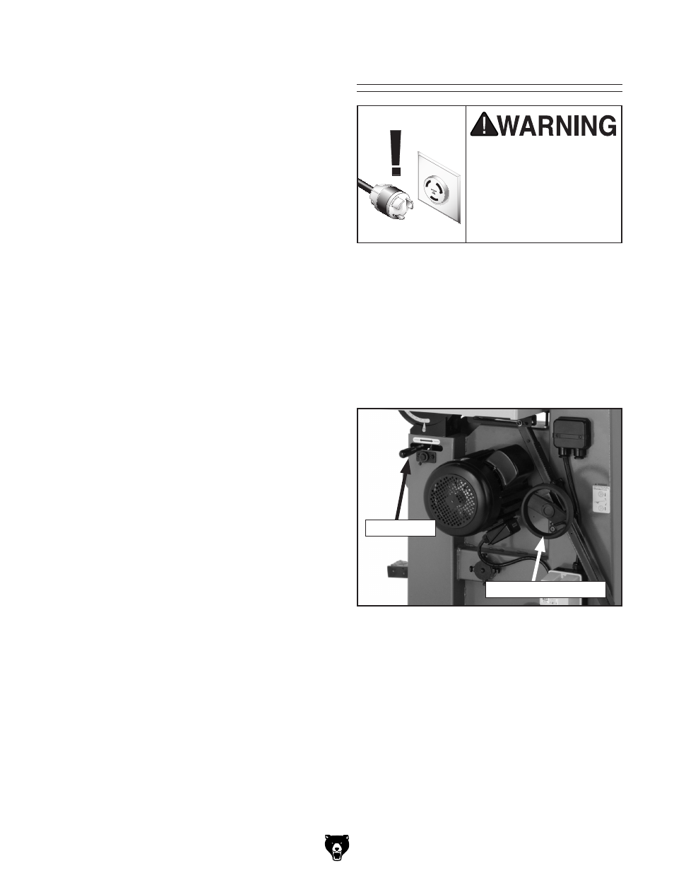
2. Loosen the table tilt lock lever shown in
Figure 42.
Table Tilt
3. To tilt the table to the right, turn the table tilt
handwheel clockwise (
Figure 42).
4. To tilt the table to the left, turn the table tilt
handwheel clockwise one turn, lower the
positive stop bolt, then turn the handwheel
counterclockwise.
5. Secure the table tilt lock lever.
6. Follow "Positive Stop" instructions on Page
17 for resettting the stop bolt and table for
horizontal (0º) operations.
Figure 42. Table tilt controls.
Lock Lever
Table Tilt Handwheel