Installation, Danger, System voltage settings – GE Industrial Solutions ZTX Series User Manual
Page 8
■
■
6
GE Zenith Controls
■
■
ZTX Operation and Maintenance Manual (72R-1000)
Installation
(cont’d)
DANGER
HAZARDOUS VOLTAGE
(Can Cause Severe Injury or Death)
Turn OFF all power before installation, adjustment, or removal of transfer switch or any of its components.
System Voltage Settings
ZTX controller boards are preconfigured to the system
voltages specified at the time of order. Exact system volt-
ages are normally set at the factory, however, depend-
ing on the actual application and system nominal volt-
age, ZTX control boards are capable of being adjusted
slightly, to meet different source characteristics for
voltage as well as frequency. (See Table 5)
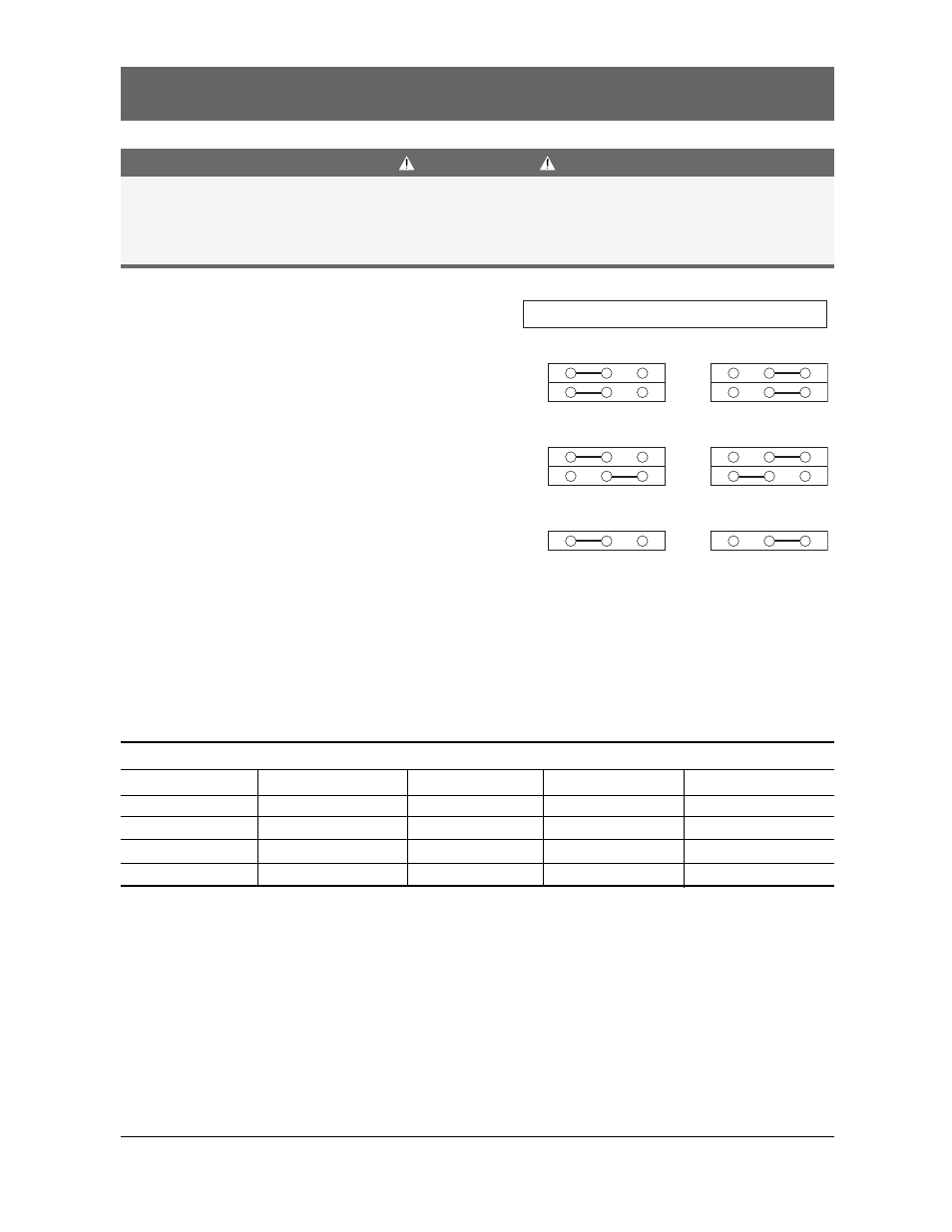
Figure 6 (on right) shows the variations each of the 3
basic types of controllers can be adjusted to within its
nominal voltage range. Position Jumpers JP1 and JP2,
as needed for voltage. Position JP3 for frequency.
As with any other Jumper setting, always remove power
completely from the controller before making changes.
Note: Do not change voltage Jumper positions
without consulting service or technical support.
Arbitrarily changing voltage jumpers can adversely
affect ATS operation.
Type 1
Type 2
Type 3
Type 4
Frequency
120V
208 - 240VAC
380 - 416VAC
440 - 480VAC
JP1
JP2
JP1 JP2
JP1 JP2
JP1 JP2
JP3
B
B
208
A
B
380 B
B
440
B
A
50 Hz
A
-
-
220
B
A
416 A
B
480
A
A
60 Hz
B
-
-
240
A
A
-
-
-
-
-
-
-
-
Table 5
Figure 6
240/480
B
A
JP1
JP2
208/416
B
A
JP1
JP2
120/380
B
A
JP1
JP2
220/440
B
A
JP1
JP2
Voltage / Frequency Selection Jumper Settings
50Hz
B
A
JP3
60Hz
B
A
JP3