Installation procedures, Installing countertop dispensers without legs, Before you begin – Follett C/E12CI400A User Manual
Page 5
5
Installing countertop dispensers without legs
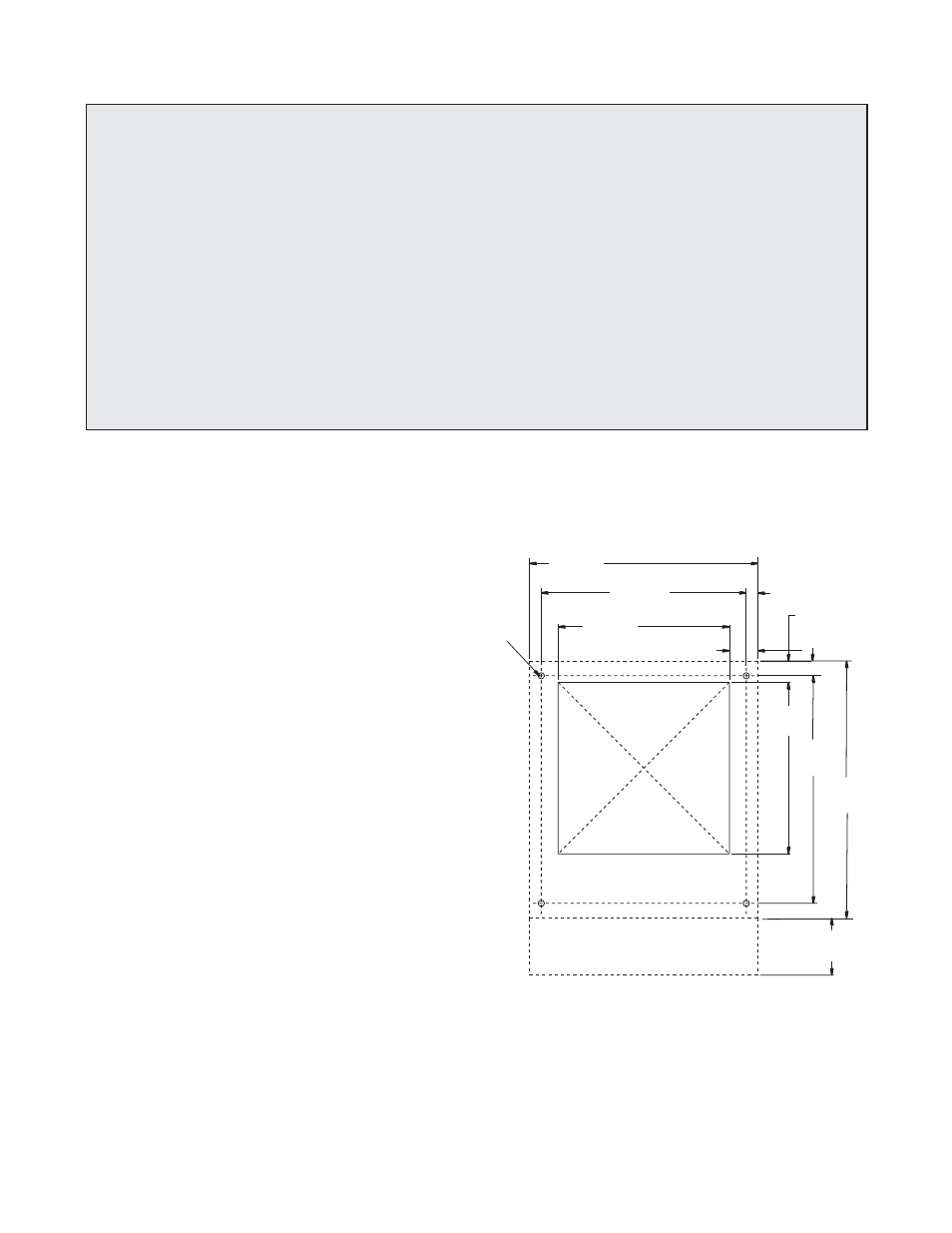
cutout for
connections
through
bottom
404mm
458mm
(4")
39mm (1.5")
305mm
305mm
366mm
(16")
21mm (0.8")
51mm (2")
407mm
(14.4")
(12")
(12")
(15.9")
(18")
102mm
26mm (1")
12mm (.437")
diameter
Fig. 1 – Counter information
Before you begin
• All dispensers must be installed level in both directions to ensure proper operation.
• Service and ventilation clearances: 6" (153mm) on right side of dispenser, 6" (153mm) at top for ventilation
and 12" (305mm) at top recommended for service.
• Countertop units installed without legs provide the option of taking utilities out bottom or back of dispenser
(on wall mount units and countertop units with legs, utilities exit from back). See counter cut out drawings for
bottom exiting utilities on units with and without drain pans. For installations where utilities exit through back
of dispenser, refer to back view drawings.
• Wall mount models without drain pan are designed for use above sinks.
• Counter depth must allow front of sink to be a minimum of 23.5 (597mm) from wall.
Installation procedures
1. Position dispenser in desired location,
mark dispenser outline on counter and
remove dispenser.
2. Regardless of whether utilities will exit
through back or bottom of dispenser,
drill four 7/16" holes in counter to
anchor dispenser to counter (Fig. 1)
3. For utilities existing through bottom
only:
(a) Make cut out as shown in
Fig.
1.
(b) Move plug from drain T to
back of unit (Fig. 2).
4. For all units: Apply a thick bead
approximately 6mm (1/4") diameter
of NSF listed silicone sealant
(Dow Corning RTV-732 or equivalent)
6mm (1/4") inside marked outline of
dispenser.
5. Carefully lower dispenser on counter in
proper position and secure to counter
with four (4) 3/8" -16NC bolts.
6. Smooth excess sealant around outside
of dispenser.