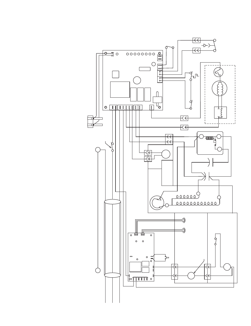
Wiring diagram – sensorsafe model, Ho w the unit w o rk s — sensors afe model – Follett C/E12CI400A User Manual
Page 15
Ho
w the unit w
o
rk
s — SensorS
AFE model
SensorS
AFE
™
models pr
o
vide
“t
ouchless”
ice and w
a
ter dispensing
. W
hen a cont
ainer is placed within the actuation z
one belo
w the ice or w
a
ter chut
e
, an in
visib
le
,
ra
ndoml
y-gener
at
ed infr
ar
ed signal is emit
ted, r
e
flect
ed of
f the cont
ainer and det
ect
ed b
y
the sensor
. The sensor then sends a
signal t
o
the contr
ol boar
d t
o
acti
va
te
the appr
opr
iat
e components t
o
dispense ice or w
a
te
r.
LEDs on the boar
d indicat
e when the boar
d is r
ecei
ving a signal fr
om the s
ensor
s
.
A saf
et
y,
shut-of
f f
eatur
e aut
omaticall
y shuts of
f dispensing af
ter one min
ut
e of contin
uous acti
va
tion.
Dispensing can be r
est
ar
ted b
y
mo
ving the cont
ainer a
w
a
y
and
then r
etur
ning it t
o
the actuation z
one
.
Dispensing can be t
empor
ar
ily suspended b
y
depr
essing and r
eleasing the clean s
witch, locat
ed under the lef
t side of the t
op fr
ont co
ve
r.
Depr
essing and r
eleasing
the b
u
tt
on a second time will r
etur
n the dispenser t
o
nor
mal oper
ating st
at
e
. If the clean s
witch is not depr
essed a second tim
e
, the dispenser will aut
omaticall
y
re
sume nor
mal dispense oper
ation (CLN LED goes out) af
ter t
w
o min
ut
es
. An LED on the contr
ol boar
d will light t
o
indicat
e that
the dispensing has been suspended
b
y
acti
vation of the clean s
witch.
The bin signal cir
cuit is complet
ed thr
ough the nor
mall
y closed cont
acts of the bin ther
most
at and the bin signal s
witch.
W
hen
ice b
uilds up ar
ound the bin
ther
most
at, the cont
acts open, cut
ting the bin signal.
WHITE
COMPRESSOR
COMP
. ST
AR
T RELA
Y
ST AR
T
RUN
COMP . ST
ART
CAP A
CIT
OR
Black
R
S
C
MAIN FRAME
(INTERNAL)
MOUNTED ON
COMPONENTS
O
V
ER-LO
A
D
COMPRESSOR
WHITE #16
FA
N
ST
AR
T
RELA
Y
RU
N
ST
AR
T
MOUNTED ON MAIN FRAME
YELLO
W
BLA
CK
GEAR MO
T
O
R
BLUE
BIN SIGNAL SWITCH
BIN
THERMO-
ST
A
T
ORANGE 18
ORANGE 19
WHITE #15
BLACK #13
GREEN #27
WHITE #12
BLA
CK #10
SAFETY SWITCH
HIGH PRESSURE
RED #17
BLA
CK #38
WHITE #39
x
x
MAIN FRAME
GRN T
O
PO
WER SWITCH
ELEC
. BO
X
GRN IN
W
A
TER SENSOR
2.
HIGH PRESSURE SAFETY SWITCH:
OPEN:
425psi CLOSES:
297psi (A
UT
ORESET)
SEE LABEL FOR PR
OPER ORIENT
A
T
ION
1.
COMPRESSOR ST
AR
T RELA
Y IS GRA
VITY SENSITIVE.
NO
TE
T
.O
.L.
1
2
5
COMP . R
UN
CAP A
CITOR
Silver
CLEAN SWITCH
LID INTERLOCK SWITCH
WHEELMO
T
O
R
SOLENOID
WHITE #34
M
BLA
CK #41
BLA
CK #33
BLACK #35
WHITE
#37
S
BLACK
#36
WA
T
E
R
GND
WM
WTR
SOL
BLACK #9
BLACK #8
NEUTRAL
#40
YELLOW
1
#40
YELLOW
4
CLN
PWR
L1
SENSOR
SPLASH P
ANEL
1
4
MAIN FRAME
COMPONENTS
MOUNTED ON
SENSOR
WA
T
E
R
COMPONENTS
MOUNTED ON
ICE
WTR
ICE
Compressor
Switch
ORANGE 14
VIOLET 23
VIOLET 22
RED 20
RED 21
RED 42
RED 43
WHITE 44
BLA
CK 45
BLA
CK 46
BLA
CK 47
ORANGE 49
BLA
CK #11
WHITE #26
ORANGE 48
SOFTWARE
WTR
B-E
B-T
I.D.
2ND
60M
20M
C
DR
V
FA
N
COMP
LABEL
I.D
.
PO
WER
DR
WTR PR
OBE
L1
L2
GREEN/YELLO
W
BR
O
W
N
BLUE
230 V~
50 Hz
2
4
3
Wiring diagram – SensorSAFE model
15