Icemaker operational and diagnostic sequences – Follett C/E12CI400A User Manual
Page 16
16
Icemaker operational and diagnostic sequences
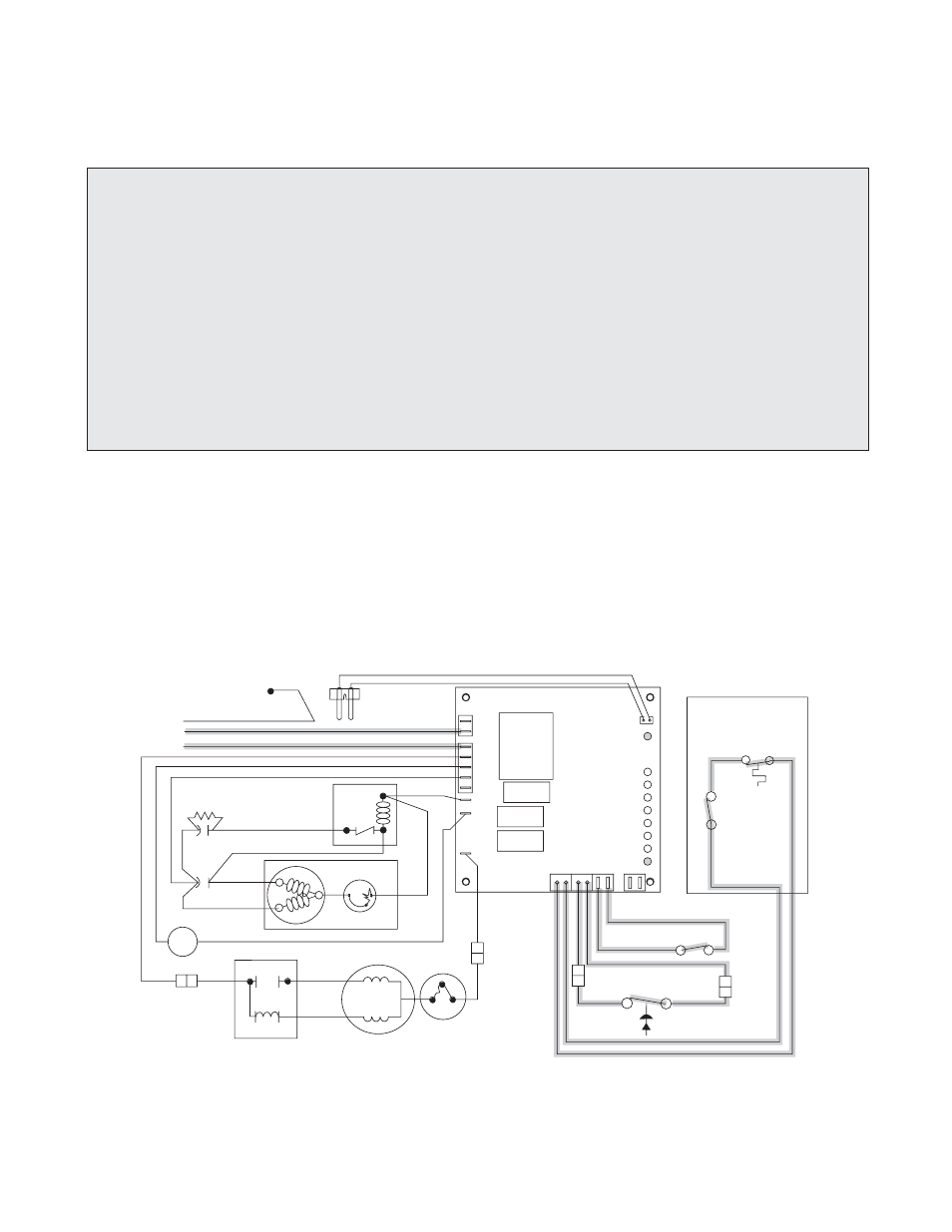
The wiring diagrams that follow illustrate the circuitry of Follett icemakers used with 12 series ice dispensers. Both
normal operation (Stages 1 – 6) and non-normal diagnostic sequences showing torque-out (Stages 7 – 10) for
use in troubleshooting are shown.
WTR
B-E
B-T
2ND
60M
20M
C
POWER
DR
WHITE
BLACK
YELLOW
WHITE
4
3
2
T.O.L.
START
RUN
GEARMOTOR
COMPRESSOR
R
POTENTIAL
START RELAY
RUN
CAP.
CAPACITOR
START
C
S
2
1
5
T.O.L.
L1
L2
COMP
FAN
DRV
RED
BIN
T-STAT
BIN
SIGNAL
SWITCH
WATER
SENSOR
G
GREEN/YELLOW
GRND IN
ELEC BOX
BROWN
BLUE
WHITE
WHITE
BLACK
BLACK
ORANGE
RED
BLACK
BLA
CK
BLACK
BLACK
VIOLET
VIOLET
ORANGE
ORANGE
RED
RED
BLUE
BLACK
FAN
M
ORANGE
BLA
CK
L
N
HIGH PRESSURE
SAFETY SWITCH
COMPRESSOR
SWITCH
DISPENSER
Circuitry notes
• Compressor switch should read closed in ON position.
• Bin signal is 16V DC.
• Flashing water LED at any time indicates that water signal to board has been lost for more than one
second.
• Ten-second delay: There is a 10 second delay in reaction to loss of water (WTR) or bin (B-E) signals. If
signals are not lost for more than 10 seconds, no reaction will occur.
Normal operation – Stage 1
Power is supplied to L1 of the control board. The ice level control in the dispenser is closed and calling for ice,
completing the bin signal circuit to the control board. The control board will now go through the start-up sequence.
Less than 30 seconds will elapse as the water sensor located in the float reservoir checks for water in the
reservoir. The bin empty LED (B-E), and power LED (PWR) will be on.