2 pwm value register (pwmvn), 3 pwm reload register (pwmrn), 4 pwm compare register (pwmcn) – Maxim Integrated MAX31782 User Manual
Page 88: 5 pwm register locations, 3 pwm output code example, 9 .3 pwm output code example -7, Table 9-3 . pwm register addresses -7, 3pwmoutputcodeexample, 2pwmvalueregister(pwmvn), 3pwmreloadregister(pwmrn)
MaximIntegrated 9-7
MAX31782 User’s Guide
Revision 0; 8/11
9.2.2PWMValueRegister(PWMVn)
The PWM value register, PWMVn, holds the 16-bit value of the PWM’s counter . Enabling or disabling the PWM with
the PWMEN bit does not reset the PWMVn register . The PWMVn register must be cleared by software . This register is
cleared to 0000h on all forms of reset and has unrestricted read/write access .
9.2.3PWMReloadRegister(PWMRn)
The PWM reload register, PWMRn, is a 16-bit register that is used as a comparison to the PWMVn register . A reload of
the PWMVn register occurs when PWMVn matches PWMRn . This register is cleared to 0000h on all forms of reset and
has unrestricted read/write access .
9.2.4PWMCompareRegister(PWMCn)
The PWM compare register, PWMCn, is a 16-bit register that is used as a comparison to the PWMVn register . Depending
upon the mode of PWM operation, the PWM .n pin is driven high or low when a match between PWMVn and PWMCn
occurs . This register is cleared to 0000h on all forms of reset and has unrestricted read/write access .
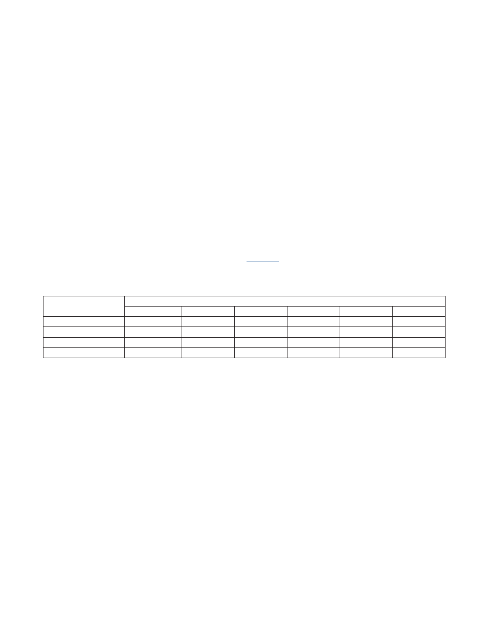
9.2.5PWMRegisterLocations
The addresses for the PWM output registers are given as “Mx[yy],” where x is the module number (from 0 to 5 decimal)
and yy is the register index (from 00h to 1Fh hexadecimal) .
shows the addresses of these registers for each
of the six PWM outputs (PWM .n) .
9.3PWMOutputCodeExample
Creating a 40% duty cycle 25kHz signal:
PWMCN0_bit.PWMPS = 0;
//PWM.0 input clk = sysclk
PWMR0 = 159;
//PWM period = 160 sysclks
PWMC0 = 64;
//duty cycle = 64/160
PWMCN0_bit.PWMCR = 1;
//set to reset mode
PWMCN0_bit.PWMCS = 0;
//set to reset mode
PWMCN0_bit.PWMEN = 1;
//enable PWM.0
Table9-3.PWMRegisterAddresses
REGISTERNAME
INDIVIDUALPWMOUTPUTNUMBER
n=0
n=1
n=2
n=3
n=4
n=5
PWMCNn
M3[09h]
M3[0Bh]
M4[09h]
M4[0Bh]
M5[09h]
M5[17h]
PWMVn
M3[08h]
M3[0Ah]
M4[08h]
M4[0Ah]
M5[08h]
M5[16h]
PWMRn
M3[01h]
M3[03h]
M4[01h]
M4[03h]
M5[0Bh]
M5[15h]
PWMCn
M3[00h]
M3[02h]
M4[00h]
M4[02h]
M5[0Ah]
M5[14h]