1 detailed description, 1 description of master i2c interface, 2 default operation – Maxim Integrated MAX31782 User Manual
Page 70: 3 i2c clock generation, 8 .1 detailed description -2, 8 .1 .1 description of master i, C interface -2, 8 .1 .2 default operation -2 8 .1 .3 i, C clock generation -2, Figure 8-1 . i
MaximIntegrated 8-2
MAX31782 User’s Guide
Revision 0; 8/11
SECTION 8: I
2
C-COMPATIBLE MASTER INTERFACE
The MAX31782 provides an I
2
C-compatible master controller that allows the MAX31782 to communicate with a slave
device . The I
2
C master interface can be setup to provide system interrupts after each I
2
C event .
8.1DetailedDescription
8.1.1DescriptionofMasterI
2
CInterface
The master I
2
C interface uses the MSDA and MSCL pins . These pins are the master I
2
C controller’s connection to the
SDA and SCL pins of an I
2
C bus . In addition to driving these pins, the I
2
C master port also senses the state of both
MSDA and MSCL . This allows the I
2
C master port to offer bus error detection and allows a slave device to clock stretch .
The MSDA and MSCL pins are open-drain output pins and require external pullup resistors to achieve a high logic level .
Unless explicitly stated, all references to SDA and SCL in this section refer to the SDA and SCL lines of the I
2
C bus, not
the MAX31782’s I
2
C slave interface SDA and SCL pins .
8.1.2DefaultOperation
The I
2
C master controller is disabled by default . The I
2
C master controller is enabled by setting the I2CEN and I2CMST
bits in the I2CCN_M register to a 1 . Prior to the I
2
C master controller being used for communication, some software
setup is required . This setup includes setting the clock rate, timeout period, and which I
2
C events should generate
interrupts . The MAX31782 master I
2
C controller is not intended to be used on an I
2
C bus that has multiple masters
connected to the bus .
8.1.3I
2
CClockGeneration
In an I
2
C system, the master is responsible for generating the SCL signal . The MAX31782 I
2
C master controller provides
complete control over the clock rate and duty cycle . The I
2
C master controller generates SCL from the system clock .
The bit rate is controlled by the I
2
C clock control register (I2CCK_M) .
The high period of SCL clock is defined by the high byte of the I
2
C clock control register (I2CCKH), whereas the
low period of SCL is defined by the low byte (I2CCKL) . The minimum clock high period is three system clocks while
the minimum low period has to be at least five system clock periods . The I
2
C clock characteristics can be defined by
the following equations:
• SCL Low Time = System Clock Period x (I2CCKL[7:0] + 1)
• SCL High Time = System Clock Period x (I2CCKH[7:0] + 1)
• I
2
C Clock Rate = System Clock Frequency/(I2CCLK[7:0] + I2CCKH[7:0] + 2 )
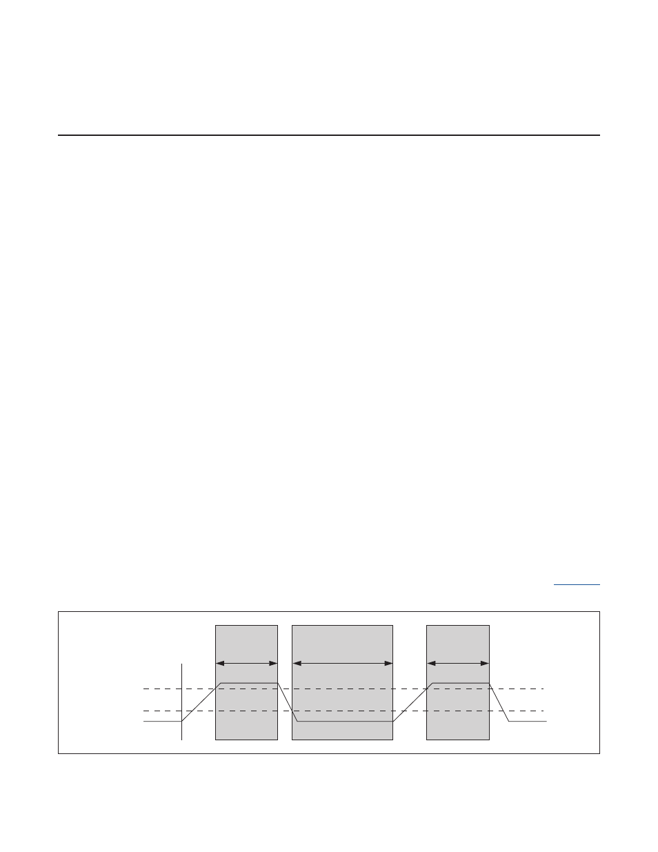
One feature of the master I
2
C controller is that it also monitors SCL while the clock is being output . This allows the control-
ler to ensure that the SCL level is at the desired level prior to beginning the count for SCL Low or High Time .
illustrates the SCL sampling performed by the master I
2
C controller . When SCL is released by the master I
2
C controller,
Figure 8-1. I
2
C Clock Generation
I2CCKH
I2CCKL
SCL
RELEASED
VIH_MIN
VIL_MAX
SCL
I2CCKH