4 timeout, 8 .1 .4 timeout -3, Figure 8-2 . master i – Maxim Integrated MAX31782 User Manual
Page 71: 4timeout
MaximIntegrated 8-3
MAX31782 User’s Guide
Revision 0; 8/11
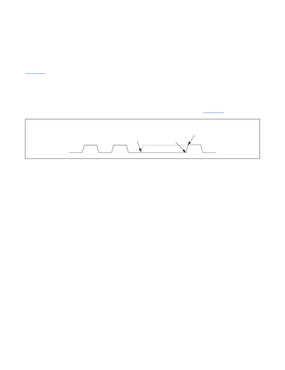
there is a rise time that is determined by the capacitive loading and pullup resistance on the SCL line . When the control-
ler senses the SCL line has reached a high logic level, the count for SCL High Time begins . The same is true for a falling
edge . The SCL Low Time only begins after the controller senses the SCL line at a low logic level .
also illustrates that the calculated I
2
C clock period will not be exactly accurate because the rise and fall time
of SCL is not taken into consideration . The actual clock period will be the period set by the I2CCK_M register plus any
rise and fall time .
The master I
2
C controller’s ability to monitor the state of SCL allows the master to operate with slave devices that clock
stretch . A slave device may clock stretch, or hold SCL low, while it is busy or processing data . The master I
2
C controller
will always release SCL after holding it low for the SCL Low Time duration . By monitoring the state of SCL, the master I
2
C
controller realizes that SCL has not been released and does not begin the SCL High Time count . Only after the master
controller detects a high state on SCL will it begin the I2CCKH count . This is illustrated in
.
8.1.4Timeout
The master I
2
C controller has a programmable timeout function that allows the controller to recover from a bus error . The
timeout period is determined by the setting of the I
2
C master timeout register (I2CTO_M) using the following equation:
Timeout Period = I
2
C Bit Rate x (I2CTO[7:0]+1)
where I
2
C Bit Rate is determined by the setting of the I2CCK_M register . The timeout can be disabled by clearing the
I2CTO_M register to 0 . The I
2
C timeout timer starts counting:
• When the I2CSTART bit is set to 1 . The I
2
C controller monitors the status of SDA and SCL until it can generate a
START condition . If the c o n t r o l l e r has to wait longer than the period specified in the timeout register, the I
2
C
controller concludes that there is a bus error and sets the I2CTOI flag .
If the I
2
C controller has started a transfer (after the first bit rising edge), it waits for the current byte transfer to
finish (after the 9th bit (acknowledge) has been transmit) before generating the START condition . In this case, the
timeout timer starts counting after the end of the 9th bit low time .
• After the master I
2
C controller attempts to generate a STOP condition . If a STOP is not detected (I2CSPI = 1) during
the timeout period, the I2CTOI flag is set .
If the I
2
C controller has started a transfer (after the first bit rising edge), it waits for the current byte transfer to
finish (after the 9th bit (acknowledge) has been transmit) before generating the STOP condition . In this case, the
timeout timer starts counting after the end of the 9th bit low time .
• Whenever SCL goes low . If the SCL line is low for a period longer than specified in the timeout register, the I
2
C
c o n t r o l l e r concludes that there is a bus error and sets the I2CTOI flag .
For all these cases, when the I
2
C timeout period is reached, the I2CTOI flag is set . The setting of I2CTOI can generate an
interrupt if enabled . If the master I
2
C controller is in the process of transferring data when the timeout occurs, the control-
ler aborts the current transfer and clears the I2CBUSY flag . The I2CBUS flag continues to be set until a STOP condition is
detected or I2CEN is set to 0 .
Figure 8-2. Master I
2
C Clock Generation During Slave Clock Stretching
SCL
THE MASTER
RELEASES SCL, BUT
THE SLAVE IS HOLDING
SCL LOW.
THE MASTER STARTS
ITS I2CCKH COUNT.
THE SLAVE
RELEASES SCL.