3 entering i2c bootloader, 18 .1 .3 entering i, C bootloader -5 – Maxim Integrated MAX31782 User Manual
Page 156: 3 entering, I2c bootloader, Cbootloader
MaximIntegrated 18-5
MAX31782 User’s Guide
Revision 0; 8/11
Following a reset, if the system programming buffer is set for JTAG bootloading, the bootload routine is entered . The
host must now load the Debug instruction (010b) into the TAP instruction register (IR[2:0]), which enables the 10-bit
Debug shift register between TDI and TDO . When operating in JTAG bootloader mode, the debug state machines are
disabled and the sole purpose of the debug hardware is to simultaneously transfer the data byte shifted in from the host
to the in-circuit debug buffer egister (ICDB) and transfer the contents of an internal holding register (loaded by ROM
code writes of ICDB) into the shift register for output to the host . The 8 most significant bits of the 10-bit shift register
interface directly to the ICDB . The transfer between the shift register and the ICDB register occurs on the falling edge of
TCK at the Update-DR state . The debug hardware additionally clears the TXC bit in the ICDF register at this point . The
ROM loader code controls the status bit output to the host by asserting TXC = 1 when it has valid data to be shifted out .
The two least significant bits of the 10-bit shift register are status bits . The JTAG bootloader has the benefit of using
the same status bit handshaking hardware that is used for in-circuit debugging . The description of the status bits is
described in
.
Note:When using the JTAG port, the clock rate (TCK) must be kept below 1/8 of the system clock rate .
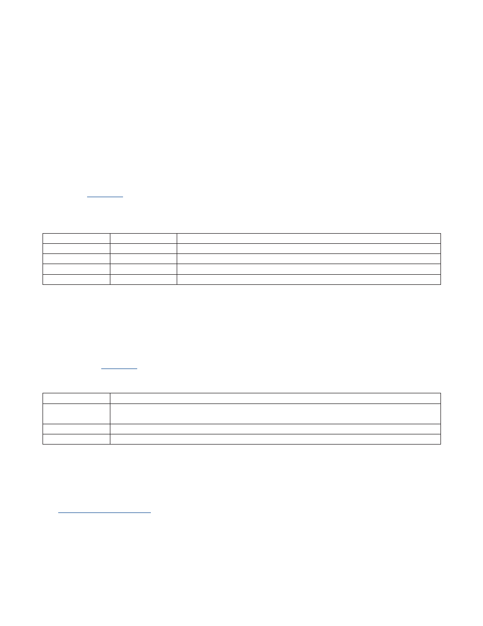
Table18-2.JTAGBootloaderStatusBits
Table18-3.SpecialFunctionsofAddress34h
18.1.3EnteringI
2
CBootloader
The MAX31782 also has built-in functionality that allows bootloading over I
2
C . Bootloading through I
2
C allows the sys-
tem to update the firmware using only the I
2
C bus without JTAG or firmware intervention . To access the bootloading
function, slave address 34h is used . This slave address is setup by hardware and cannot be changed through firmware .
As long as the slave I
2
C port is enabled, which is the default, the MAX31782 always responds to this slave address
without any firmware interaction required . This address should not be used for any purpose other than the special boot-
loading features .
details the special functions that can be performed using slave address 34h .
To enter the I
2
C bootloader, the host must first write slave address 34h with data F0h and then issue a STOP command .
When the STOP command is received, the I
2
C _SPE bit is set . The MAX31782 must then be reset . This can be done
using either the RST pin or by using the I
2
C self-reset . To do an I
2
C self-reset the host needs to write slave address 34h
with data BBh . Upon receiving an I
2
C STOP, a reset is performed .
The I
2
C bootloader can also be entered if a part has never been programmed and does not contain a valid password .
See
for more details about the password . Any device that does not have a password set
has the I2C_SPE bit set by ROM code and enters I
2
C bootloader operation . The ROM code also clears the PWL bit,
which allows full access to all of the bootloader commands .
BITS1:0
STATUS
CONDITION
00
Reserved
Invalid condition .
01
Reserved
Invalid condition .
10
Loader-Busy
ROM loader is busy executing code or processing the current command .
11
Loader-Valid
ROM loader is supplying valid output data to the host in current shift operation .
COMMANDBYTE
ACTION
F0h
Sets the I2C_SPE bit in the I2C_SPB register to enable bootloading through I
2
C . This bit is not cleared on
device reset .
BBh
Executes a reset of the MAX31782 when an I
2
C STOP is received .
All other bytes
The I2C_SPE bit in I2C_SPB is cleared . The MAX31782 NACKs this byte .