57 typical wiring schematic (cont) – Bryant COMMERCIAL SINGLE PACKAGE ROOFTOP GAS HEAT/ELECTRIC COOLING 581B User Manual
Page 57
57
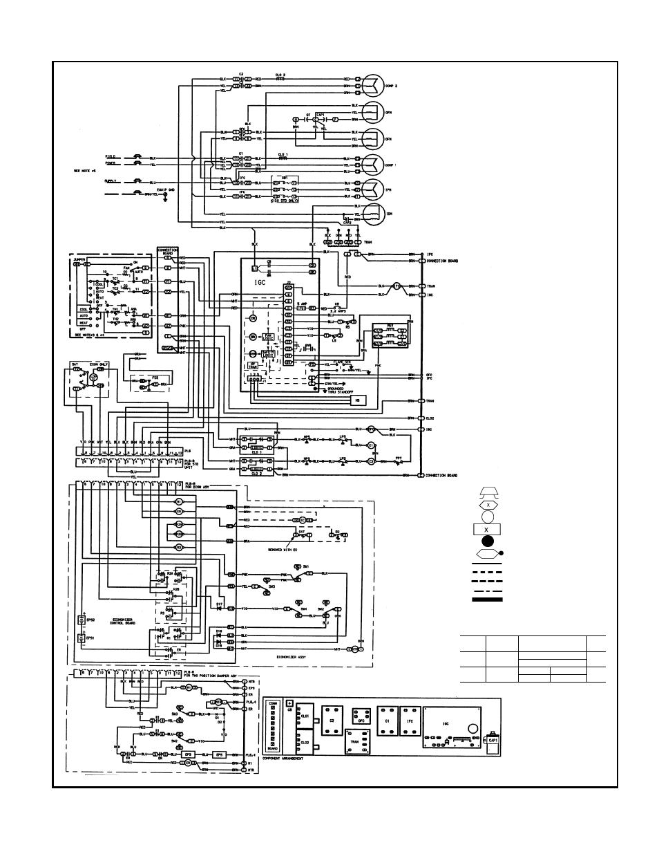
TYPICAL WIRING SCHEMATIC (cont)
581B090-150 Typical Wiring Schematic
LEGEND
AHA
— Adjustable Heat Anticipator
BR
— Burner Relay
C
— Contactor, Compressor
CAP
— Capacitor
CB
— Circuit Breaker
CC
— Cooling Compensator
CLO
— Compressor Lockout
COMP
— Compressor Motor
CONN
— Connection
CR
— Control Relay
D
— Diode
EC
— Enthalpy Control
ECON
— Economizer
EPS
— Emergency Power Supply
EQUIP
— Equipment
ER
— Economizer Relay
FPT
— Freeze-Protection Thermostat
FS
— Flame Sensor
FSS
— Filter Status Switch
FU
— Fuse
GND
— Ground
GVR
— Gas Valve Relay
HPS
— High-Pressure Switch
HS
— Hall Effect Sensor
HV
— High Voltage
I
— Ignitor
IDM
— Induced-Draft Motor
IFC
— Indoor (Evaporator) Fan
Contactor
IFM
— Indoor (Evaporator) Fan Motor
IFMOVL — Indoor-Fan Motor Overload
Switch
IGC
— Integrated Gas Unit Controller
LPS
— Low-Pressure/Loss-of-Charge
Switch
LS
— Limit Switch
MGV
— Main Gas Valve
MTR
— Motor
NC
— Normally Closed
NO
— Normally Open
OAT
— Outdoor-Air Thermostat
OFC
— Outdoor (Condenser) Fan
Contactor
OFM
— Outdoor (Condenser) Fan Motor
P
— Plug
PL
— Plug Assembly
QT
— Quadruple Terminal
R
— Relay
RS
— Rollout Switch
SAT
— Supply-Air Thermostat
SEN
— Sensor
SW1
— Switch Fully Open
SW2
— Switch Fully Closed
SW3
— Switch Minimum Vent Position
SW4
— Switch Maximum Vent Position
TC
— Thermostat-Cooling
TH
— Thermostat-Heating
TRAN
— Transformer
Field Splice
Terminal (Marked)
Terminal (Unmarked)
Terminal Block
Splice
Splice (Marked)
Factory Wiring
Field Control Wiring
Field Power Wiring
Accessory or Optional Wiring
To indicate common potential
only. Not to represent wiring.
CIRCUIT
BREAKER
VOLTS
MFG. PT. NO.
MUST
TRIP
AMPS
CB
24 V
Potter & Brumfield
3.2
W2BX-1024-3.2
CB1
(150 Std)
208/230-3-60
Heinemann
Airpax
17.3
CF3-2204-15
209-3-2599-485