Sm series – General Pump SM Repair Manual User Manual
Page 31
GENERAL PUMP
A member of the Interpump Group
SM SERIES
Page 31
2.2.2 Assembling the Head-Liners-Valves
To reassemble the various components, reverse the operations listed previously, paying particular attention to
the correct assembly of the spacer for liners: the hole Ø6 (seal cooling circuit) must correspond to the same
hole for the head (with o-ring).
Heads - liners: proceed with assembly and calibration of the head fixing screws and then with
calibration of the liner fixing screws.
For the values of the screw tightening torques and sequencing, follow the instructions contained in Section 3.
2.2.3 Dismantling The Plunger Unit - Supports - Seals
The plunger unit does not require any routing maintenance. Maintenance is limited to visual inspection of
cooling circuit drainage. If abnormalities/variations on the outlet pressure gauge or cooling circuit draining hose
pulsing (if flexible) are detected, the seal packings will have to be checked and replaced.
Proceed as follows to extract plunger groups:
Separate the head and the spacer for the pump casing liners as indicated in point 2.2.1 (from fig. 95 to fig 101).
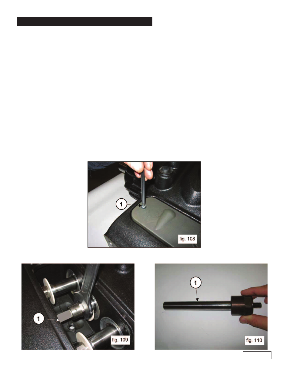
Remove the inspection cover, unscrewing the 2 fixing screws (1, fig. 108).
Ref 300894 Rev.A
06-12
Remove the pumps with a fork spanner (1, fig. 109) and check conditions (1, fig. 110). Replace if necessary.