Welch Allyn PROPAQ CS User Manual
Page 51
Service Manual
Calibration
47
8.
Verify that the input current from the variable dc power supply is less than 1.8 A and
that the green LED on the monitor’s right side panel is on.
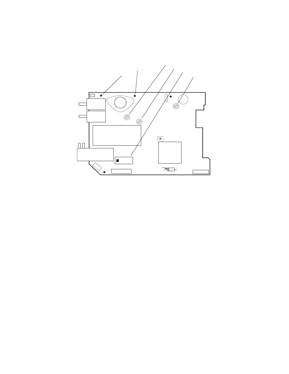
Figure 2. Recharger PCB measurement and adjustment locations
9.
Connect the DMM positive lead to P12 pin 1 or 5.
10. Connect the DMM reference (negative) lead to non-isolated ground at TP2.
11. Adjust RP5 to 9.400 ± 0.010 V dc.
12. Move the DMM positive lead to TP4.
13. Adjust RP3 to 2.393 ± 0.015V dc.
14. Move the positive lead back to P12 pin 1 or 5.
15. Vary the input voltage from 12 to 28 V and check that the output voltage remains
constant. The battery load voltage must not vary more than 0.100 V dc.
16. Decrease the power supply voltage from 12 to 7 V while checking the right side panel
green LED. The LED should turn off between 7 and 12 V.
17. Disconnect the adapter cable from the monitor’s right side panel.
18. Remove the 4.9
Ω test load and replace it with the 4.65Ω test load.
19. Reconnect the adapter cable.
20. Adjust RP1 to 9.350 ± 0.010 V dc.
21. Remove the 4.65
Ω.
22. Reconnect the cable to P12.
CATHODE
D33
T3
VLV2
VLV1
VLV3
RP7
NIBP PUMP
P11
P10
P12
+BAT
TP1
P14
TP3
Q1
GND
TP2
OVR SET
TP4
PT2
RP5
RP3
PIN 1
RP1
RP5
TP2
TP4
RP3
RP1
P12