17 ide connector (p19) – Intel STL2 User Manual
Page 82
Jumpers and Connectors
STL2 Server Board TPS
5-74
Pin
Signal
Pin
Signal
15
GND
49
GND
16
DIFFSENSA
50
GND
17
TRMPWRA
51
TRMPWRA
18
TRMPWRA
52
TRMPWRA
19
No Connection
53
No Connection
20
GND
54
GND
21
ATNAP
55
ATNAN_L
22
GND
56
GND
23
BSY
57
BSYAN_L
24
ACK
58
ACKAN_L
25
RSTAP
59
RSTAN_L
26
MSGAP
60
MSGAN_L
27
SELAP
61
SELAN_L
28
CDAP
62
CDAN_L
29
REQAP
63
REQAN_L
30
IOAP
64
IOAN_L
31
SCDAP8
65
SCDAN8_L
32
SCDAP9
66
SCDAN9_L
33
SCDAP10
67
SCDAN10_L
34
SCDAP11
68
SCDAN11_L
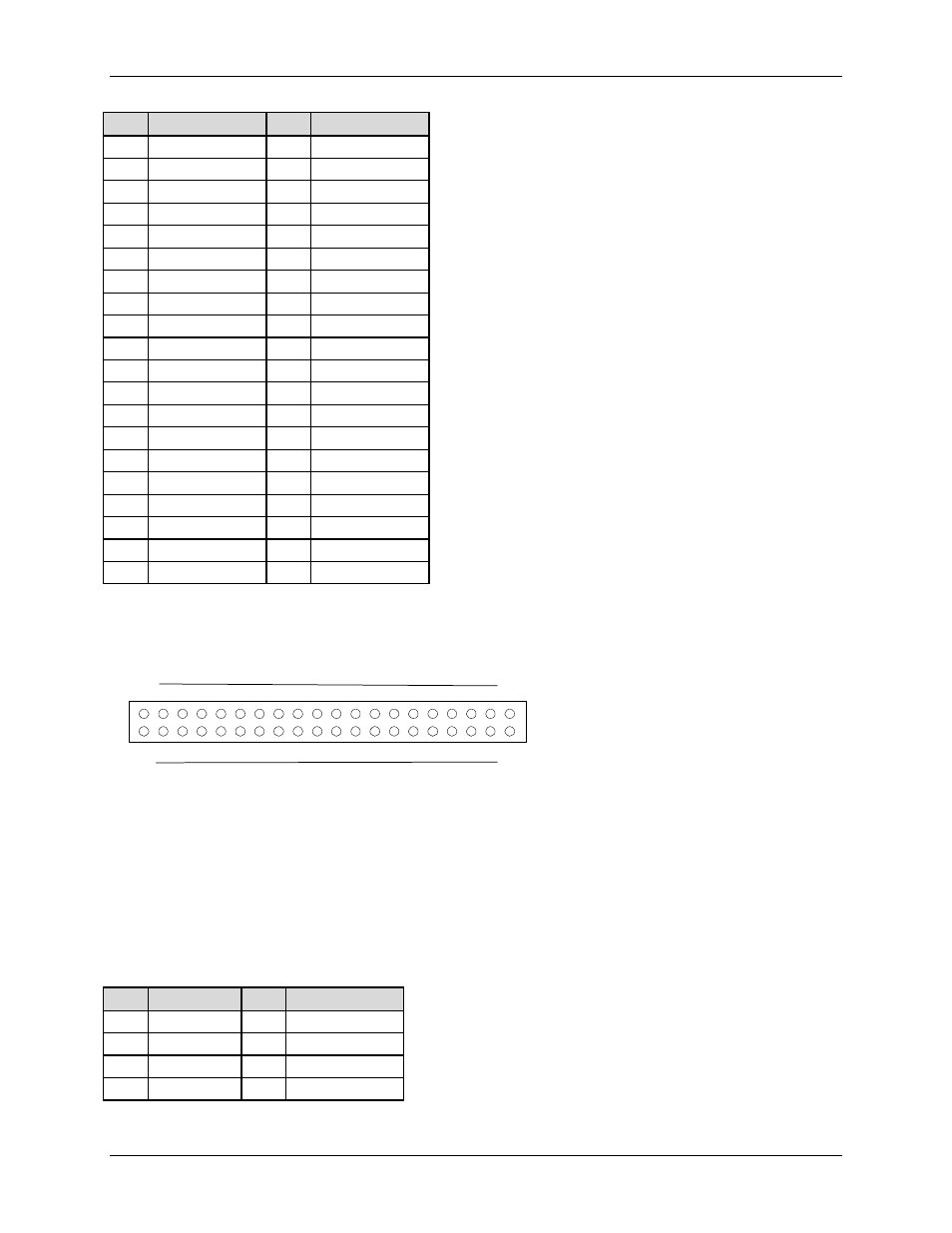
5.2.17 IDE Connector (P19)
1
20
21
40
Figure 5-4. IDE Connector Pin Diagram
If no IDE drives are present, no IDE cable should be connected. If a single IDE drive is
installed, it must be connected at the end of the cable.
Table 5-22. IDE Connector Pinout
Pin
Signal
Pin
Signal
1
RESET_L
21
GND
2
DD7
22
DD8
3
DD6
23
DD9
4
DD5
24
DD10