Intel STL2 User Manual
Page 43
STL2 Server Board TPS
Basic Input Output System (BIOS)
Revision 1.0
4-35
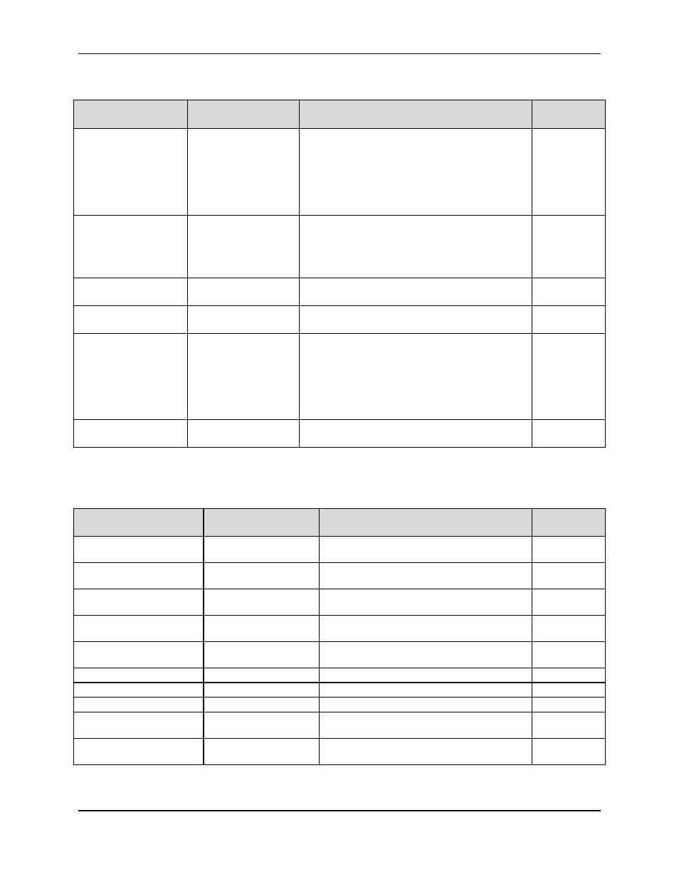
Table 4-3. Primary Master and Slave Adapters Submenu Selections
Feature
Choices or Display
Only
Description
User Setting
Type
Auto
None
CD-ROM
ATAPI Removable
IDE Removable
Other ATAPI
User
Select the type of device that is attached to the
IDE channel
If User is selected, the user will need to enter the
parameters of the IDE device (cylinders, heads
and sectors).
Mult-Sector Transfers
Disable
2 Sectors
4 Sectors
8 Sectors
16 Sectors
Specifies the number of sectors that are
transferred per block during multiple sector
transfers.
LBA Mode Control
Disabled
Enabled
Enable/Disable Logical Block Addressing instead
of cylinder, head, sector addressing.
32 Bit I/O
Disabled
Enabled
Enable/Disable 32Bit IDE data transfers
Transfer Mode
Standard
Fast PIO 1
Fast PIO 2
Fast PIO 3
Fast PIO 4
FPIO 3/ DMA 1
FPIO 4 / DMA 2
Select the method of moving data to and from
the hard drive. (If Type: Auto is select, optimum
transfer mode will be selected)
Ultra DMA Mode
Disabled
Enabled
Enable/Disable Ultra DMA mode (If Type: Auto is
select, optimum transfer mode will be selected)
Table 4-4. Processor Settings Submenu Selections
Feature
Choices or Display
Only
Description
User Setting
Processor Speed
XXX
(Display Only). Indicates the processor
speed.
Processor 1 Type
XXX
(Display Only). Indicates the CPUID of the
installed processor.
Cache Ram
XXXKB
(Display Only). Indicates the cache RAM
size.
Processor 2 Type
XXX
(Display Only). Indicates the CPUID of the
installed processor.
Cache Ram
XXXKB
(Display Only). Indicates the cache RAM
size.
Processor #1 Status
Normal
1
(Display Only)
Processor #2 Status
Normal
1
(Display Only)
Clear Processor Errors
Press Enter
Clears the processor error information.
Processor Error Pause
Enabled
Disabled
If enabled, the POST operation pauses if a
processor error occurs.
Processor Serial Number
Disabled
Enabled
Disables/Enables Processor Serial Number.
Note:
1. Possible Values: Normal, None, or Error.