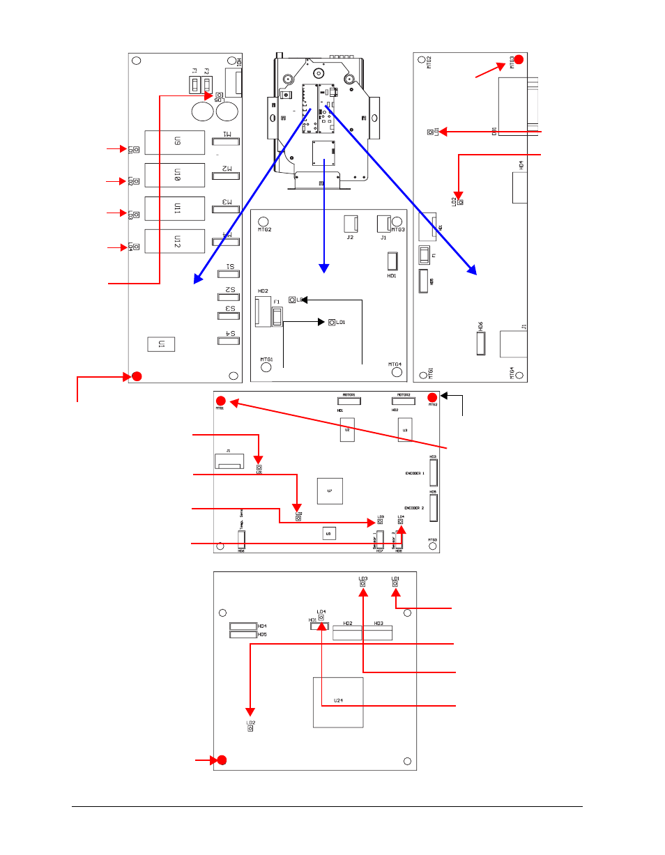
Figure 5-8: addressing screw and led locations -10 – High End Systems DL1 User Manual
Page 70
5-10 General Maintenance and Troubleshooting
DL.1 User Manual
Figure 5-8 Addressing screw and LED locations.
2-Phase
LED 1
LED 2
LED 4
LED 5
RS-232
LED 1
Board
LED 2
Fan Board
LED 1
LED 2
LED 3
3-Phase
LED 2
LED 4
LED 3
LED 1
LED 1
LED 2
LED 4
LED 5
LED 3
CPU
Board
Board
Pan Addressing Screw
Tilt Addressing Screw
CPU Addressing Screw
2-Phase
Addressing
Screw
Board
RS-232
Addressing
Screw