Honeywell VRX180 User Manual
Page 42
Installation
Video Recorder - User Manual
28
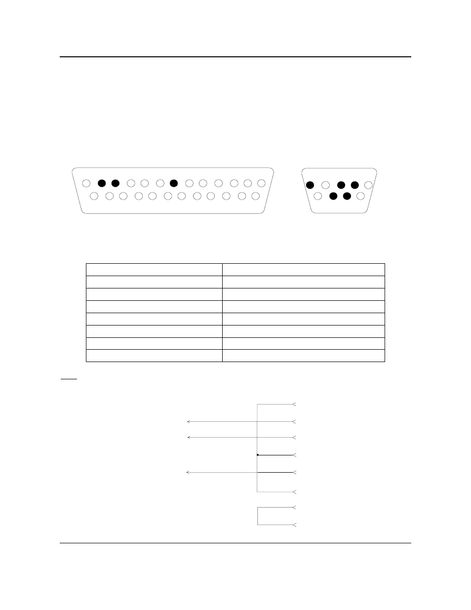
2.5.7.1.2 Interface connector
• With DB9 connector
Interface cable connectors pin arrangement and signal functions.
1 2 3 4 5 6 7 8 9 10 11 12 13
14 15 16 17 18 19 20 21 22 23 24 25
5 4 3 2 1
9 8 7 6
VIDEO RECORDER SIDE
DB25 male connector face view
PC SIDE
DB9 female connector face view
RECORDER PC
Pin n°
Pin n°
2 2
3 3
5 4
7 5
20 6
20 8
Note : Check compatibility with your PC as far as no standard for DB9 connector exists yet.
2
3
7
1 DCD
2 RD
3 TD
4 DTR
5 S.G.
6 DSR
7 RTS
8 CTS
VIDEO RECORDER
PC