Ups rear panel, Repo port – HP R5500 User Manual
Page 9
Component identification 9
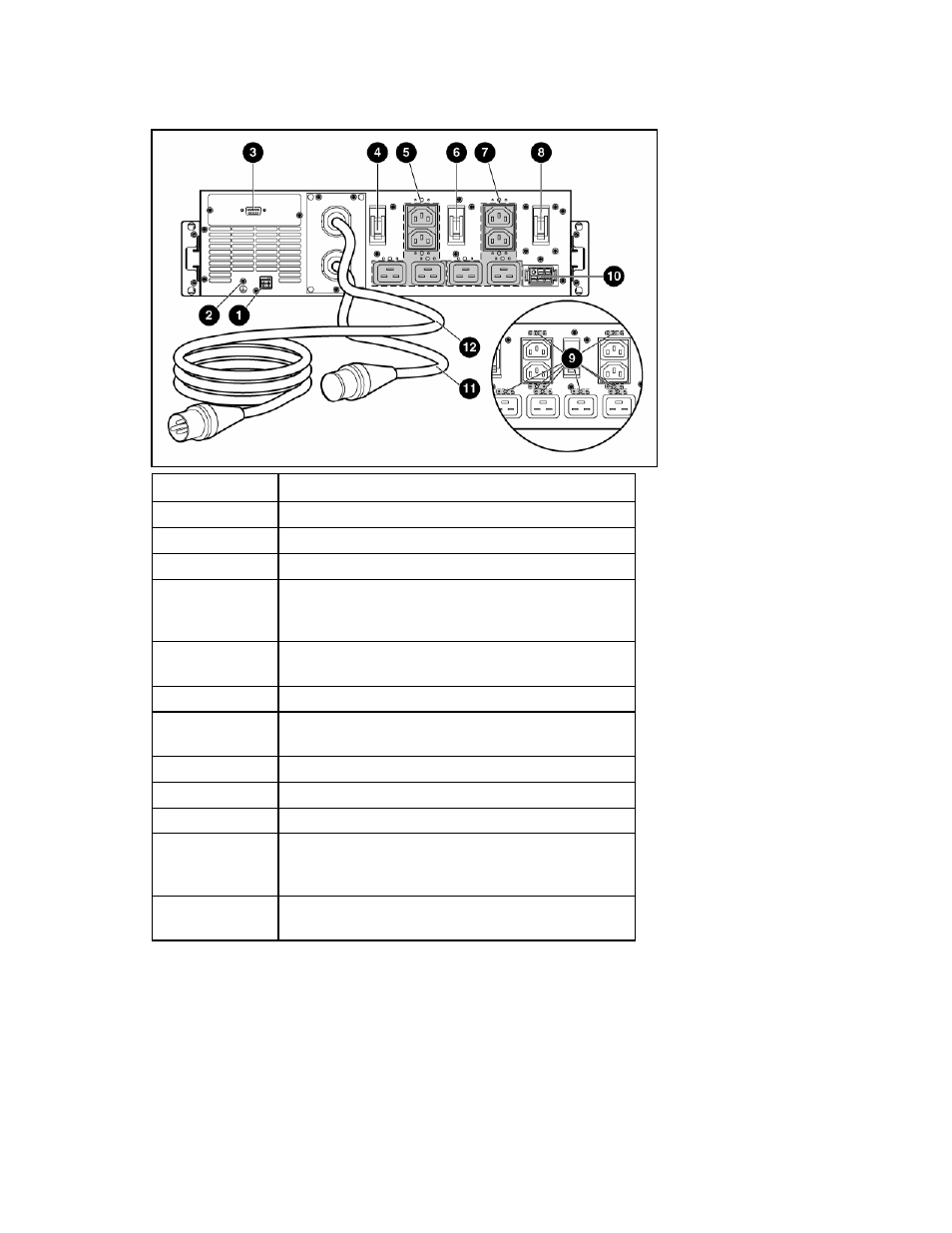
UPS rear panel
Item Description
1 REPO
port
2
Ground bonding screw
3
Communications port/option slot
4
Load segment 1 circuit breaker (controls the C19 and
C13 receptacles, but does not control the large output
receptacle)
5
Load segment 1 (two IEC-320-C19 receptacles, two IEC-
320-C13 receptacles, and one large output receptacle)
6
Load segment 2 circuit breaker
7
Load segment 2 (two IEC-320-C19 receptacles and two
IEC-320-C13 receptacles)
8
Battery circuit breaker
9 Cord
retention
clip
attachment locations
10 ERM
connector
11
Large output NEMA L6-30R receptacle (NA/JPN) or IEC-
309-32A receptacle (INTL) associated with load segment
1
12
Input power line cord with NEMA L6-30 plug (NA/JPN)
or IEC-309-32A plug (INTL)
REPO port
The UPS includes an isolated REPO port. When properly wired, the REPO feature enables the power at
the UPS output receptacles to be switched off from a remote location. To use this feature, the REPO port
must be connected to a remote, normally open switch (not supplied). The REPO switch is used in
conjunction with a main disconnect device that removes the AC source from the input of the UPS. When
the switch is closed: