Eurotech Appliances VIPER / VIPER-LITE PXA255 User Manual
Page 82
VIPER Technical Manual
Power and power management
© 2007 Eurotech Ltd Issue E
82
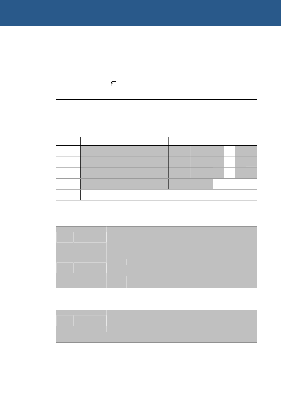
To communicate with the VCORE DAC, use the following pins to emulate the LTC1659
interface:
GPIO
LTC1659 DAC pin function
GPIO6 Data
GPIO11
Clock
GPIO19 Chip
Select
Before putting the PXA255 into sleep mode, ensure the R_DIS bit in the ICR register is
set to ‘1’. The PXA255 is not designed to interface to 8-bit peripherals, so only the least
significant byte from the word contains the data.
Interrupt configuration and reset register
Byte lane
Most Significant Byte
Least Significant Byte
Bit
15 14 13 12 11 10
9
8
7
6
5
4
3 2 1
0
Field
-
-
-
-
-
-
-
-
-
-
-
-
CF_
RST
R_DIS
AUTO_
CLR RETRIG
Reset
X
X
X
X
X
X
X
X
0
0
0
0
0 0 0
0
R/W
-
-
-
-
-
-
-
-
R R/W
Address 0x14100002
ICR bit functions
Bit Name
Value
Function
0
No interrupt retrigger (embedded Linux/VxWorks)
0
RETRIG
1
Interrupt retrigger (Windows CE)
0
No auto clear interrupt / Toggle GPIO1 on new interrupt
(embedded Linux and VxWorks).
1
AUTO_CLR
1
Auto clear interrupt / pulse low for 1.12µS on GPIO1 on
new interrupt from a new interrupt source (Windows
CE).
0
Board reset normal
2 R_DIS
1
Board reset disable (Set before entering CPU sleep)
0
CompactFlash reset controlled by board reset
3
CF_RST
1
Reset CompactFlash
4 - 7 -
X
No function