Exatron 3000b – Extron electronic 3000B User Manual
Page 76
Exatron 3000B
www.exatron.com
4-10
Chapter 4 Handler Setup
A
DRS
D
ESCRIPTION
ROM
RAM
O
PTIONS
C
OMMENTS
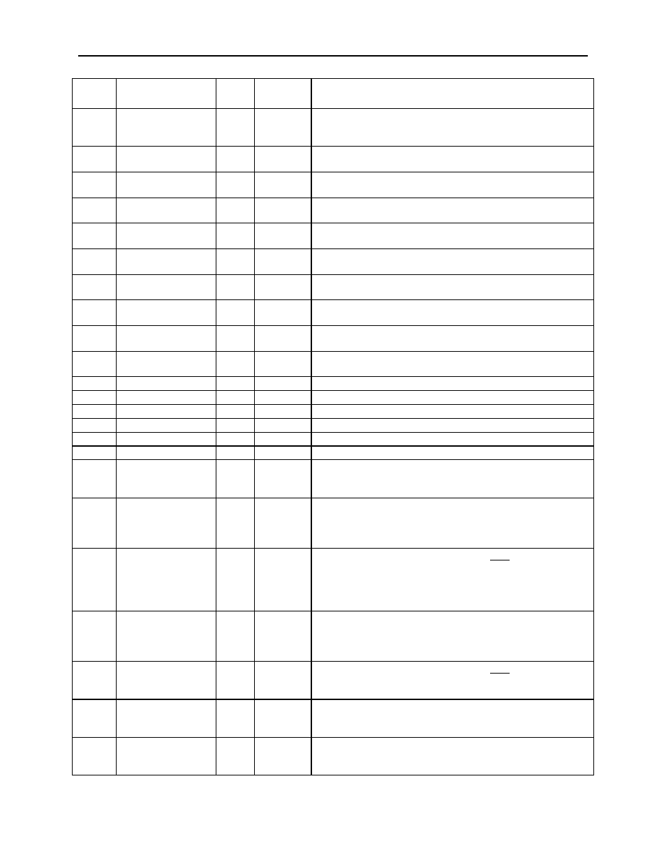
00BF
FF
00C0
Sort 1 Bins 1-8
EF
00 to FF
Input Sort 1 to handler output bins. BIT MAP.
Output cover LEDs will blink output Bin locations.
00C1
Sort 2 Bins 1-8
10
00 to FF
Input Sort 2 to handler output bins. BIT MAP.
Output cover LEDs will blink output Bin locations.
00C2
Sort 3 Bins 1-8
10
00 to FF
Input Sort 3 to handler output bins. BIT MAP.
Output cover LEDs will blink output Bin locations.
00C3
Sort 4 Bins 1-8
10
00 to FF
Input Sort 4 to handler output bins. BIT MAP.
Output cover LEDs will blink output Bin locations.
00C4
Sort 5 Bins 1-8
10
00 to FF
Input Sort 5 to handler output bins. BIT MAP.
Output cover LEDs will blink output Bin locations.
00C5
Sort 6 Bins 1-8
10
00 to FF
Input Sort 6 to handler output bins. BIT MAP.
Output cover LEDs will blink output Bin locations.
00C6
Sort 7 Bins 1-8
10
00 to FF
Input Sort 7 to handler output bins. BIT MAP.
Output cover LEDs will blink output Bin locations.
00C7
Sort 8 Bins 1-8
10
00 to FF
Input Sort 8 to handler output bins. BIT MAP.
Output cover LEDs will blink output Bin locations.
00C8
Pick Up Step
1000
1
30 to 39
Label Pick up “1000” step setting 3000BL only
00C9
Pick Up Step 100
0
30 to 39
Label Pick up “100” step setting 3000BL only
00CA
Pick Up Step 10
1
30 to 39
Label Pick up “10” step setting 3000BL only
00CB
Pick Up Step 1
2
30 to 39
Label Pick up “1” step setting 3000BL only
00CC
Apply Step 100
4
30 to 39
Label Apply “100” step setting 3000BL only
00CD
Apply Step 10
3
30 to 39
Label Apply “10” step setting 3000BL only
00CE
Apply Step 1
7
30 to 39
Label Apply “1” step setting 3000BL only
00CF
Label Que
01
00 to 19
Sets the number of labels printed on power up. Setting
depends on version of 3000BL. In most cases set to 01,
prints only 1 label. 3000BL only
00D0
Add Label
FF
00, AA,
FF
For 3000BL only
00 = Test and Label in one operation
FF = Test only, skip the label site
AA = Label only, no test
00D1
Bit Check
00
00, FF
For P
ROGRAMMER
RS-232 Interface only.
Performs Illegal Bit Test at the start of the programming
cycle.
00 = Bit Check ON. (Data I/O)
FF = Bit Check OFF. (Bytek)
00D2
Interface Type
26
23, 25,
26
Sets default interface to be used by the handler.
23 = P
ROGRAM
RS-232 Interface (Data I/O, Bytek)
25 = E
XATRON
RS-232 Interface
26 = H
ANDLER
P
ORT
Interface
00D3
P/V/L
02
02, 04,
08
For P
ROGRAMMER
RS-232 Interface only.
Selects Program, Verify, or Load Master operation.
02 = Program. 04 = Verify. 08 = Load Master.
00D4
Plunge
Steps1000
0
30 to 39
For Plunge to Board Type 4 Changeover Kits. Sets the
1000s digit of the Z-motor plunge to contact steps. Set
as ASCII Number.
00D5
Plunge Steps 100
3
30 to 39
For Plunge to Board Type 4 Changeover Kits. Sets the
100s digit of the Z-motor plunge to contact steps. Set
as ASCII Number.